
Summary of Contents for FSLaser 36x24
- Page 1 FSLaser Professional Series 36x24 and 48x36 Lasers Setup and Installation Guide 3/21/2013...
- Page 2 R2.0 – 21 March 2013 ©2013 FSLaser LLC 4325 West Patrick Ln., Suite 155 Las Vegas, NV 89118 Phone: (702) 605-0644 Fax: (650) 215-9917 Technical Support Phone: (702) 879-2762 Technical Support Email: support@fslaser.com http://fslaser.com/resources/software-manual-downloads [ii]...
- Page 3 (This Page Intentionally Left Blank) [iii]...
-
Page 4: Table Of Contents
Contents Table of Figures ..........................vi Fire Warning........................... 1 Introduction ........................... 3 Icons Used in This Manual ......................3 Part 1: Safety ..........................4 Overview ............................ 4 Laser Safety ..........................4 General Operation Precautions ....................4 Electrical Safety .......................... 6 Fire Safety ..........................7 Compliance Statement ....................... - Page 5 Part 4: Rotary Attachment Setup ....................32 Rotary Attachment Connection....................32 Appendix A: Troubleshooting ....................... 34...
-
Page 6: Table Of Figures
Table of Figures Figure 1 - Main Assembly......................11 Figure 2 - Knife-edge Table (included) ..........Error! Bookmark not defined. Figure 3 - Honeycomb Table (included) ..................12 Figure 4 - Work Area Interior ......................12 Figure 5 - Rear Inputs ........................13 Figure 6 - Laser Head Assembly .................... - Page 7 (This Page Intentionally Left Blank) [vii]...
-
Page 8: Fire Warning
ALWAYS keep a properly maintained and inspected fire extinguisher on hand. FSLaser recommends a Carbon Dioxide fire extinguisher or a multi-purpose dry chemical fire extinguisher. The Carbon Dioxide extinguishers are more expensive than a dry chemical, but offer certain advantages should you ever need to use an extinguisher. - Page 9 (This Page Intentionally Left Blank)
-
Page 10: Introduction
Introduction Thank you for your purchase of a FSLaser Professional Large Format (ProLF) Series Laser System. It is our wish that this product adds value to your business activities for years to come. Please take time to read this manual in its entirety to safely use your laser to its full potential. -
Page 11: Part 1: Safety
Part 1: Safety Overview Please carefully read all instructions before attempting to operate the laser. Never operate or test the laser without the water pump activated or with anything other than pure distilled water as a coolant. Never attempt to operate the laser with the lid open or attempt to override the magnetic lid interlock switch. - Page 12 Class I. It is the operator’s responsibility to ensure that the installation and operation of the FSlaser ProLF unit is performed in accordance with all applicable laws. Copies of ANSI Standard Z136.1-2000 are...
-
Page 13: Electrical Safety
Electrical Safety The AC input power to the FSLaser ProLF unit is potentially lethal and is located on the far right within the cabinet. DO NOT open any of the machine’s access panels while the unit is plugged in. Opening a panel may expose the operator to the unit’s AC input power. -
Page 14: Fire Safety
ALWAYS keep a properly maintained and inspected fire extinguisher on hand. FSLaser recommends a Carbon Dioxide fire extinguisher or a multi-purpose dry chemical fire extinguisher. Carbon Dioxide extinguishers are more expensive than a dry chemical, but offer certain advantages should you ever need to use an extinguisher. -
Page 15: Compliance Statement
Compliance Statement The FSLaser ProLF Laser System is a class 3R laser product, as defined in International Standard IEC 60825-1. The FSLaser ProLF Laser System complies with 21 CFR 1040.10 and 1040.11, the Federal Performance Standards for Light-Emitting Products, except for deviations pursuant to Laser Notice No. -
Page 16: Part 2: Getting Started
Part 2: Getting Started Setting Up Your Laser System Setup of the ProLF laser usually takes less than 1 hour, but there are a few things you will need to take care of before it arrives: Purchase distilled water for cooling the laser. Your laser comes with a pump and tubing for circulating the water through the tube and back into a reservoir. -
Page 17: Parts And Accessories
Parts and Accessories Your laser shipped with the following included parts and accessories: Table 1 - Included Accessories Description Quantity ProLF laser engraving machine Exhaust fan Exhaust Tubing Air compressor Water pump + tubing 1 set Honeycomb cutting table and Knife- 1 set edge table Power cable... -
Page 18: Get To Know Your Laser
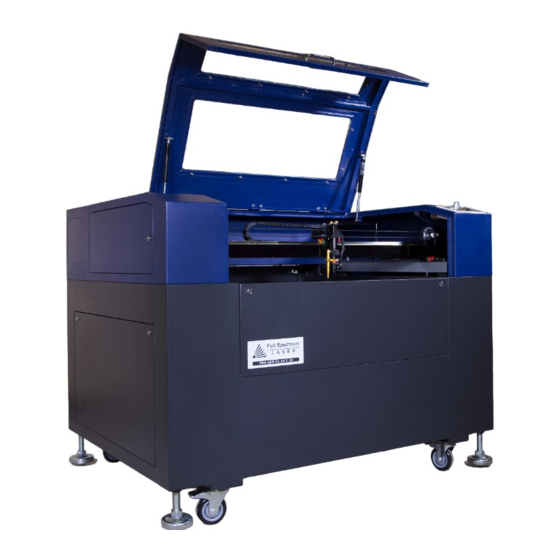
Get to Know Your Laser The following figures will introduce you to the major parts of your ProLF 36x24/48x36 Laser System. Figure 1 - Main Assembly 1. Work area lid with protective window 2. RetinaEngrave CapTouch Control Panel 3. Mirror 2 4. - Page 19 Figure 2 - Honeycomb Table (included) Figure 3 - Work Area Interior 1. X axis drive motor 2. Y cable carrier 3. Magnetic safety interlock sensor [12]...
- Page 20 Figure 4 - Rear Inputs 1. AC power input 2. AC input re-settable fuse 3. Exhaust port 4. Water inlet 5. Air inlet 6. Water outlet [13]...
- Page 21 Figure 5 - Laser Head Assembly 1. Mirror 3 2. Mirror 3 adjustment thumbscrew 3. Air assist input 4. Air assist nozzle 5. Autofocus plunger [14]...
-
Page 22: Connecting The Exhaust
Connecting the Exhaust It is mandatory that the exhaust blower is connected and operating whenever you run a job on your laser. The exhaust blower removes smoke and fumes from the case and exhausts them to the outside of the building. You should never operate your laser without a working exhaust. Figure 6 - Exhaust Port The exhaust port on your laser is a 6in flange, located on the rear of the unit (Figure 6). -
Page 23: Connecting The Water Pump And Air Assist Compressor
Connecting the Water Pump and Air Assist Compressor Your laser uses a water-cooled continuous beam CO laser tube. The tube requires a flow of room-temperature water to regulate the temperature of the resonance chamber. Your purchase includes a water pump for cooling the laser tube. A low-flow air compressor for vector cutting gas assist is available as an optional accessory. -
Page 24: Water Chiller Upgrade (Optional)
Water Chiller Upgrade (Optional) The water chiller replaces the water pump. If your laser is shipped with a water chiller then the pump is normally not included. Unscrew the cap at the top of the water chiller and fill with water. -
Page 25: Third-Party Air Assist Systems
30psi. Low-quality compressed air can damage your focus lens. Connecting Electrical Power The FSLaser ProLF 24x18 and available accessories are configured to accept 110VAC at 60Hz. 220VAC units connect to power through an included converter (single-phase 220VAC). - Page 26 Notes: Power On/Off: the laser’s main power is controlled by a key-lock switch on the top panel in the front-right, near the control panel interface. The control system power is controlled by the large red button (e-stop) located on the top of the case in the far right.
-
Page 27: Part 3: Quick Start And Setup
Part 3: Quick Start and Setup Overview Now that you have set up your laser and accessories and have installed the control software, the next step is to ensure that your laser is working properly. The tube test and mirror alignment procedures should take less than 30 minutes and will ensure that your laser is performing optimally. - Page 28 RetinaEngrave3D Software The latest version of RetinaEngrave3D can be downloaded using your credentials from http://fslaser.com/resources/software-manual-downloads. This page also has the latest version of the software manual, which includes installation, setup and use instructions. [21]...
-
Page 29: Beam Path
Beam Path The following figures detail the path of the laser beam through the laser’s chassis. The beam path and direction are defined by the white arrows while the focused beam is denoted by the red arrow. Figure 11 – Optics Set 1 1. - Page 30 Figure 12 - Optics Sets 1 and 2 Figure 13 - Work Area: Optics Sets 2 and 3 1. Optics set 2 (Mirror 2 and adjustment screws) 2. Optics set 3 (Laser head: mirror 3, autofocus, focus lens and air assist) [23]...
-
Page 31: Laser Tube Test
Figure 14 - Detail of Optics Sets 2 and 3 1. Mirror 3 2. Mirror 3 adjustment thumbscrews 3. Focus Lens (internal) Laser Tube Test In this test we are going to tape a piece of thermal paper between the laser tube aperture and the beam combiner aperture and then test fire the tube. -
Page 32: Mirror Alignment
7. A circular black mark with diffuse edges should appear on the thermal paper. If there is interference, the mark will be occluded and/or have a very sharp edge. If this is the case, your tube is working but has come out of alignment. You should hear a ‘click’... -
Page 33: Alignment Procedure
Alignment Procedure The ProLF 24x18 laser has an integrated beam combiner which greatly simplifies beam alignment. The general procedure is to first align the red beam with the invisible beam then use the red beam as the primary indicator for alignment. 1. - Page 34 Adjust beam combiner (BC) screws until red dot is same height then twist BC until both overlap Laser fire 7. Move the X gantry to the top Y position. Fire another black dot onto the thermal paper. You should now have two black dots (one from the upper Y position and one from lower Y position).
- Page 35 Black dots are closer -Move red dot between two black dots -Repeat until both on top 12. Once the mirror #1 is aligned, we will adjust mirror #2. Put a piece of thermal paper on mirror #3. Using the red dot, adjust the mirror until the red laser is somewhere on the mirror.
- Page 36 19. Move the laser head around and verify the red dot does not move away from the black dot anywhere on the laser bed. The closer you get the dots stationary, the better aligned the laser will be. You can fire black dots at the 4 corners of the laser bed and verify none of them are more than 2mm away from each other.
-
Page 37: Focusing
(Figure 15). Figure 15 - Using the Focus Ruler As an alternative to the focus ruler, you can use the included autofocus mechanism. FSLaser recommends using the focus ruler to achieve best results. Note that for thin or delicate materials you should always use the focus ruler. -
Page 38: Quick Start
Quick Start Your FSLaser system is ready to use if you have read the manual to this point and followed all of the foregoing instructions. Please remember to use caution while operating the laser and make sure that all accessories are functioning properly before running any job. The following... - Page 39 Part 4: Rotary Attachment Setup The rotary attachment requires disconnection of the Y-Axis motor from the motor driver. The attachment effectively replaces the Y-Axis by rotating the object as the laser fires. Place the rotary attachment in the machine. Align it parallel with the X axis by dragging the red dot over a straight object like a label or piece of tape on the bottom.
- Page 40 Figure 17 - Rotary Attachment Connection (behind belt) 1. Rotary attachment/Y motor electrical connection Figure 18 - Rotary Attachment Loose Electrical Connection Detail [33]...
- Page 41 Appendix A: Troubleshooting Problem Solution Machine and Control panel 1. Disengage large red emergency stop safety switch on does not turn on. front panel. Turn it clockwise to disengage. 2. Turn ON/OFF switch to the on position 3. Disconnect the fluorescent light bulb in case of any shorts.
- Page 42 [35]...
Need help?
Do you have a question about the 36x24 and is the answer not in the manual?
Questions and answers