
Summary of Contents for Duetech Beres STP Lite
- Page 1 STP Lite User Manual Revision 1.02 STP Lite 'Smart Terminal Plus' Lite Stand Alone GSM/GPRS Multi-Purpose Controller with Logic Flow Lite Configuration Software User Manual Revision 1.02...
- Page 2 ©2009 Duetech Beres, Ltd. All rights reserved. The copyright and proprietary rights in the guide belong to Duetech Beres, Ltd. It is strictly forbidden to copy, duplicate, sell, lend or otherwise use this guide in any way, shape or form without the prior consent of Duetech Beres, Ltd.
-
Page 3: Table Of Contents
4.1 G ........30 ECTION ETTING TARTED WITH OGIC STP Lite Menus and Toolbar ................31 Verifying that there is communication with the STP Lite ........32 4.2 C .............. 34 ECTION ONFIGURATION ETTINGS Configuration Settings Screen ................34 4.3 R .............. - Page 4 SEFUL XAMPLES Finding out the STP’s Phone Number ..............61 Using the STP Lite’s DISARM Option to Set an Alarm ........62 Using the STP Lite’s Timer Option..............62 Using the STP Lite’s DISARM Option..............63 CHAPTER 5: TROUBLESHOOTING ............65 Problem No' 1: Unable to read or write data from the configuration menu ..
-
Page 5: Chapter 1: Introduction
Uses of the STP Lite Section 1.2 The STP Lite owes its name to the fact that it employs a minimal number of inputs and outputs. However, this poses no limitation on the range of uses for the STP Lite. You can employ the STP Lite in: ... - Page 6 STP Lite User Manual Revision 1.02 This manual contains special instructions that are important for the safe and proper handling of the device. The warning symbols you will encounter in the manual have the following meaning: DANGER: Indicates warning of possible danger to the life and health of the user if the relevant safety measures are not taken.
-
Page 7: Stp Lite's Features And Benefits
(PLC, PC, GPS to any RS232 device) An event report, which allows you to make the STP Lite send a report to you via Serial Communication. (RS232). This way, the user can create Word/Excel reports based on the data from the STP. -
Page 8: Chapter 2: Overview
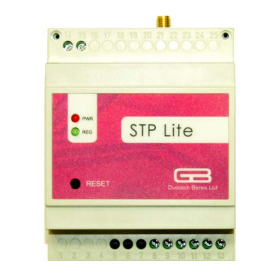
STP Lite User Manual Revision 1.02 Chapter 2: Overview This chapter provides a brief Overview of the STP Lite and includes the following: General Description Hardware Description STP Lite General Description Section 2.1 The STP Lite is a stand-alone, multipurpose terminal with extended logic control, with cellular capabilities. - Page 9 STP Lite User Manual Revision 1.02 Figure 2: Side View of the STP Lite Showing Dimensions...
-
Page 10: Inputs
STP Lite User Manual Revision 1.02 Inputs The STP Lite supports 8 different types of input events, four external, and four internal: Table 1: STP Lite Inputs External Input Description DIGITAL INPUT: A digital sensor. These can include: Thermostat ... -
Page 11: Output Events
STP Lite User Manual Revision 1.02 Output Events The STP Lite allows for 10 different types of output events and messages. Six of the outputs are to external devices, while four are internal messages that the STP Lite employs itself. The six outputs to... -
Page 12: Hardware Description
Duetech Beres controllers. Here is a brief summary of the hardware the STP Lite employs: Packaging: The STP Lite is packaged in a small (72 x 90 x 50 mm) polystyrene case. The casing allows for a DIN rail mount, to insure ultimate safety and stability of the device. - Page 13 85°C, allowing it to withstand the harshest conditions. GSM technology: The STP Lite device is based on GSM/GPRS network therefore a SIM card (not included in the STP Lite kit) must be inserted before applying power. Programmable: The STP Lite is a programmable controller: you program its logic by means of the Logic Flow Lite software, and write the commands to the device.
-
Page 14: Chapter 3: Installing The Stp Lite
Package Contents Section 3.1 The STP Lite unit comes in a kit with the accessories listed in the table below. The table lists the contents of the kit and their part numbers. Table 3: Package Contents... -
Page 15: Section 3.2 Hardware Installation
Mount the STP Lite by pushing or snap-fitting it onto a DIN rail (top-hat rail 35 mm). Pull out the black tab on the STP Lite device using a screwdriver, and snap the device onto the DIN rail. Ensure that the retaining mechanism of the STP Lite snaps cleanly and securely onto the DIN rail. -
Page 16: Connecting The Gsm Antenna
Figure 6: Side view of STP Lite ATTENTION: Do not force the STP Lite onto the DIN rail. Forcing the device on the rail may crack the black tab or the STP Lite casing, and may seriously compromise the stability of the device. -
Page 17: Installing The Sim Card
Installing the SIM Card Open the STP Lite casing by gently pushing in the two tabs at the top (where the GSM Antenna is attached) or bottom (where are the attachments for the digital output and input) of the device. - Page 18 Input/Output-side of STP Lite Device Figure 9: Input/Output side view of STP Lite unit Place a SIM card in the SIM card holder. SIM Card Slot Figure 10: Inside of STP Lite unit, showing the slot for the SIM card...
-
Page 19: Connecting The Rj45 Cable
SIM doesn't contain any saved SMS messages. These messages may cause the STP Lite to malfunction. Connecting the RJ45 cable Connect the RJ45 cable (supplied with the STP Lite) to the STP Lite unit via the socket labeled "COM". Relay Output Digital... -
Page 20: Attaching The Rj45 To Db9 Adapter
Attach the RJ45 to DB9 adapter the 9-pin, RS232 port on your computer. Figure 12: RJ45 to DB9 Adaptor Hook up the STP Lite to your computer by inserting the other end of the RJ45 cable into the adapter. Attaching the Relay Output The Smart Terminal Plus Lite has one relay (dry-contact) output. - Page 21 Connects the circuit when the relay is activated Disconnects when the relay is inactive. The STP Lite device can be used to control digital output. In the following illustration, there are two loads attached to the STP—one to the Normally Open terminal, and one to the Normally Closed terminal.
- Page 22 STP Lite User Manual Revision 1.02 The following circuit illustrates another use of the relay output. The Lamp is connected to the Normally Open terminal block, and the power source for the lamp is connected to Common. Upon receiving the digital input, the relay output's Normally Open terminal will close, turning the lamp on.
-
Page 23: Installing The Digital Input
STP Lite User Manual Revision 1.02 Installing the Digital Input The STP Lite accepts one digital input that must be within the range 0- 24 V DC. ATTENTION: Be certain not to exceed the maximum input voltage of 24 V DC. -
Page 24: Connecting The Power Supply
Once you have completed all the other installation steps, you can attach the power supply to the STP Lite unit. The STP Lite operates on the range between 9-24 V DC. The STP Lite kit contains a transformer that converts the wall current to 12 V DC. - Page 25 STP Lite User Manual Revision 1.02 The following table shows the correct connections of the transformer to the STP Lite. Table 6: Terminal Blocks for Attaching the Power Supply to the STP Lite Terminal Block Purpose Number Hole 14 GND lead from transformer...
-
Page 26: Stp Operation
When STP unit is sending a SMS or GPRS message Power on Red, steady As we'll see later on in the section dealing with the Logic Flow Lite software, the red light will flash when the STP Lite sends an SMS or GPRS message. - Page 27 Green GSM LED The green GSM LED indicates that the unit registers to the network. When you first power up the STP Lite, or press Restart, the device emits 4 beeps, and in a few seconds the green LED lights up. The green LED will remain lit continuously for five seconds, while the device is searching for the cellular network.
-
Page 28: Reset Button
STP Lite User Manual Revision 1.02 Reset Button If you encounter a problem with the functioning of the device, use the Reset button on the front of the device to reset the STP. This will allow you to restart the device without having to detach it from the power supply. -
Page 29: Chapter 4: Using Logic Flow Lite
STP Lite User Manual Revision 1.02 Chapter 4: Using Logic Flow Lite This chapter provides detailed instructions for configuring and using the Logic Flow Lite Software that comes with the STP Lite unit. Getting Started with Logic Flow Lite Section 4.1... -
Page 30: Stp Lite Menus And Toolbar
Remove All Allows you to erase all conditions from the list. Note that it removes conditions only from LogicFlow, to erase the STP Lite, click 'Write to Device' after removing all conditions to update the hardware. Phonebook Allows you to store names and phone numbers of... -
Page 31: Verifying That There Is Communication With The Stp Lite
COM1/9600: An indication of the serial port and the baud rate. Verifying that there is communication with the STP Lite When you first execute the Logic Flow Lite software, you will receive notification that the serial port is not connected to the STP Lite. - Page 32 STP Lite User Manual Revision 1.02 Device is not connected 1. Click on the command COM Port in the opening screen. The Serial Connection dialog appears, prompting you to open the COM Port. This enables communication between your computer and the STP Lite device.
-
Page 33: Section 4.2 Configuration Settings
Fields in the Configuration Settings Screen UNIT ID If you employ several STP Lite devices, you will find it useful to be able to identify which device is sending you a particular SMS or GPRS message. The UNIT ID option in the Configuration Settings Spreadsheet is what allows you to assign an identifying name to each STP Lite unit. -
Page 34: Section 4.3 Read Inputs Command
The Read Inputs command on the Logic Flow Lite main screen is an option that allows you to know the status of the digital input and relay output of the STP Lite. This information about whether the digital input and digital output are presently HIGH or LOW will be displayed on the... -
Page 35: Phonebook Setup
STP Lite User Manual Revision 1.02 Phonebook Setup The Logic Flow Lite interface allows you to provide the STP Lite with a Phonebook—a list of phone numbers of a group of users of the STP Lite. Adding a Number to the Phonebook To add a number to the Phonebook 1. -
Page 36: Removing A Phone Number From The Phonebook
In order to save the phone number and name, click on Save&Close. Logic Flow Lite saves the Phonebook data locally on your computer, and updates the STP Lite as specified. Removing a Phone Number from the Phonebook To remove a number from the Phonebook: 5. -
Page 37: Exporting A List Of Phone Numbers From The Phonebook Into A File
Setting the STP's Input Event Section 4.4 For the STP Lite to implement condition sentences, you must program the input and output events of the device. The Logic Flow Lite software allows for a set of 12 different types of inputs, and 13 different types of outputs. - Page 38 The other fields adjust automatically according to the type of input event selected. A single input event to the STP Lite can control up to four output events, in any one instruction sentence. For example, upon receiving the given input event, such as a device exceeding range...
-
Page 39: Digital" Input Event
HIGH or LOW. "OUTPUT" Input Event You can even set an output event to serve as input to the STP Lite device. This is practical, for instance: If the event is timed output and you would like to do something... -
Page 40: Main Power" Input Event
STP Lite User Manual Revision 1.02 If an incoming call will cause OUTPUT1 to be triggered, you want that the STP Lite should to do something as a response to this output change. To use the "OUTPUT 1" as an input event: 1. -
Page 41: Sms" Input Event
"SMS" Input Event A useful feature is using an SMS as the input event. You can send an SMS to the STP Lite device, and that can serve to trigger the STP Lite to give the programmed output. To set an SMS message as the input to the STP: 1. -
Page 42: Incoming Call" Input Event
STP Lite User Manual Revision 1.02 "Incoming Call" Input Event Just as you can set an SMS message to be the trigger of the STP Lite device, you can also use an incoming call to serve as the trigger. You... -
Page 43: Disarm" Input Event
DISARM is a useful command when the STP Lite is used for security or alarm system. Let's say you want to set an alarm only after you leave the area you wish to secure. Setting the input of the STP Lite to DISARM will cancel all output events—effectively turning the alarm system off. - Page 44 STP Lite User Manual Revision 1.02...
-
Page 45: Startup" Input Event
The STARTUP option allows you to execute the desired output every time the STP Lite is turned on or resets. (This is a practical feature, for example, if you want to find out the number stored on the STP Lite’s SIM card, in order to access the device—see Section 4.8, Some... -
Page 46: Section 4.5 Setting The Stp' S Output Events
Section 4.5 After configuring the desired input event for the STP Lite, and selecting the number of output events you want the STP Lite to control, you now have to select the type of output event. The Logic Flow Lite software allows for 10 different output event options from which to choose. - Page 47 Duration (Seconds) field to scroll it and choose FOREVER. 4. Click on OK. The Input and Output event will be displayed in brief on the Logic Flow Lite main screen, indicating how if the Input condition will be fulfilled, the STP Lite will do the Output event.
-
Page 48: Timer" Output Event
STP Lite User Manual Revision 1.02 "Timer" Output Event Sets Timer to a predefined value, Timers 1 & 2 count 10 minutes per unit, and timers 3 & 4 count 1 second per unit. (See Section 4.8, Some Useful Examples, p. 62). -
Page 49: Sms" Output Event
STP Lite User Manual Revision 1.02 "SMS" Output Event You can set the STP Lite to send you an SMS message when the device receives the specified input. To use the SMS Output Event: 1. Click on the arrow near the Output Event list box, and select SMS as the output event. -
Page 50: Gprs" Output Event
STP Lite User Manual Revision 1.02 "GPRS" Output Event You can have the STP Sense send a GPRS message to you via your Internet server, in the event of something triggering the specified input, or a power failure. The GPRS message is sent to the IP Address or domain name and Port that you specify. -
Page 51: Rs232" Output Event
3. Click OK. "Outgoing Call" Output Event You can have the STP Lite send you an outgoing call as the output event. When the STP Lite receives the specified input, the phone number you supply the STP Lite will receive a single ring. -
Page 52: Buzzer" Output Event
STP Lite User Manual Revision 1.02 "Buzzer" Output Event You can have the STP Lite give a buzz of a specific frequency when it receives the input event. This is the Buzzer feature of the STP. To set the Buzzer as the output event: 1. -
Page 53: Alarm" Output Event
3. Click OK. "Alarm" Output Event You can use the STP Lite device as an alarm. When you set ALARM as the output event, the STP Lite will emit a high-pitched alarm sound, until you reset the STP Lite device. -
Page 54: Set
For example, if you move the STP Lite unit temporarily to a different circuit, you will want to restore the previous set of instructions when you go back to the first device. - Page 55 STP Lite User Manual Revision 1.02 The Save As dialog box will open, prompting you to give a name to your compilation of instructions. Supply a name in the File name box, and click Save. The list of instructions will be saved as a file with the extension .cond.
-
Page 56: Loading A Saved Set Of Instructions
Remove all the instructions displayed on the screen After you've saved the previous set of instructions on the screen, you want to configure the STP Lite from scratch. You will first have to erase all the conditions presently on the screen. -
Page 57: Editing The Instruction List
2. Click Remove. The selected condition will be erased from the display. Editing the Instruction List If you want to modify one of the instructions to the STP Lite, Logic Flow Lite has a convenient editing feature. To edit the instruction list: 1. -
Page 58: Expanding/Collapsing The Instruction List
Section 4.7 Procedure for Writing the Instructions to the STP Once you have specified the inputs and outputs to the STP Lite in the Logic Flow Lite software, you now have to write the commands to the device. This is performed using the Flash command. -
Page 59: Troubleshooting A Failed Write To The Stp Lite
If the write to the device was successful, you will receive the prompt: "Flash Success". Troubleshooting a Failed Write to the STP Lite If the write to the device was not successful, you will receive a warning box, prompting you either to leave the program, or to ignore the problem and continue running the program. -
Page 60: Section 4.8 Some Useful Examples
Some Useful Examples Section 4.8 Finding out the STP’s Phone Number In the event that you received the STP Lite device and don’t know the phone number associated with it, Logic Flow Lite can help you easily find out the number. -
Page 61: Using The Stp Lite's Disarm Option To Set An Alarm
STP Lite device. Using the STP Lite’s DISARM Option to Set an Alarm One of the major uses of the STP Lite is in setting an alarm for a security system. The task may involve setting an alarm, or disabling it... -
Page 62: Using The Stp Lite's Disarm Option
5. Set the Logic Flow Lite input event as TIMER1, and the Output Event as ALARM, and click OK. The second line of the command to the STP Lite will appear on the screen. 6. Click on Write Logic to Device. - Page 63 STP Lite User Manual Revision 1.02 not inadvertently set off the alarm. The DISARM option allows you to disarm the STP Sense's outputs (in this case, to prevent it from alerting you of rising temperature). To use the DISARM to disable an alarm system: 1.
-
Page 64: Chapter 5: Troubleshooting
STP Lite User Manual Revision 1.02 Chapter 5: Troubleshooting Problem No' 1: Unable to read or write data from the configuration menu Solution suggestions In case that the unit is not new (have been used before) press the reset button and right away click on the read or write configuration to device. -
Page 65: Problem No' 3: Green Led Is Constantly On
STP Lite User Manual Revision 1.02 Call suggestions Check if the phone number you entered is correct. GPRS suggestions Check if the IP and address is correct and the target destination is open to that port. Check if the APN, at the configuration window is correct and suitable for the sim card. -
Page 66: Chapter 6: For Further Information
STP Lite User Manual Revision 1.02 Chapter 6: For Further Information For more information about our products, recommendations for accessories, components, online documentation and updates, please visit our website: www.duetech.gberes.com Revision History: Date Author 16/04/09 Initial Draft Yehuda Posnick 10/05/09...
Need help?
Do you have a question about the STP Lite and is the answer not in the manual?
Questions and answers