Table of Contents
Advertisement
Quick Links
Advertisement
Table of Contents

Summary of Contents for HFE GENPOD 100
- Page 1 GENPOD ® HFE INTERNATIONAL OWNER’S MANUAL HFEDCN0543 Revision B...
-
Page 2: Table Of Contents
CONTENTS SPECIFICATIONS ........2 SAFETY PRECAUTIONS ......4 FUEL REQUIREMENTS ....... 5 COMPONENT IDENTIFICATION ....6 INSTALLATION AND STARTING ....9 INSTALLATION .....................9 THROTTLE, COMMUNICATION, AND ENABLE SETUP .......... 11 ENGINE STARTING ..................... 12 STARTING AGAIN AFTER FIRST START ..............12 REMOVING THE ENGINE .................. -
Page 3: Specifications
SPECIFICATIONS Metric Value (SI) Value (SAE) Actual displacement 100 cc 6.1 in Momentary Peak Power @ rated 6.1 kW @ 9000 RPM 8.2 hP @ 9000 RPM Max Continuous Power 5.5 kW @ 7000 RPM 7.3 hP @ 7000 RPM Peak Torque @ RPM 7.7 NM @ 6500 RPM 5.7 ft lbs @ 6500 RPM... -
Page 5: Safety Precautions
SAFETY PRECAUTIONS General Safety Read and understand this Owner’s Manual before operating your engine. You can help prevent accidents by being familiar with the controls and observing safe operating procedures. Operator’s Responsibility: 1. The operator should know how to stop the engine quickly in case of an emergency. 2. -
Page 6: Fuel Requirements
Leaded fuels will require cylinder, piston, and port, dressing and inspection every 50 to 100 hours (depending on use case). Cylinder dressing and cleaning should be done by a trained professional or by HFE International. -
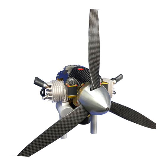
Page 7: Component Identification
COMPONENT IDENTIFICATION Fuel Filter Engine Connector Display for ® Fuel Connector GenPod Status Generator Connector ® Figure 1. GenPod Connections and Components Decompression Valves Air Filter ® Figure 2. GenPod Air Filter... - Page 8 Throttle Servo Injector Figure 3. Intake Assembly Components MAP Fitting Fuel Fitting Figure 4: Intake Assembly Components...
- Page 9 Status Display Faults: Engine Hour Meter CHT - Cylinder Head Temperature Sensor Fault Engine Speed (RPM) MAT- Manifold air Temperature Engine Status (Enabled / Sensor Fault Disabled) TPS - No Throttle Command given or throttle command error ® Battery - Power to GenPod Fault Codes will display in the too high or too low.
-
Page 10: Installation And Starting
INSTALLATION AND STARTING INSTALLATION 1. Install the GenPod Interface to your aircraft with 4x M5 flat head screws, ensuring that ® the attachment can handle up to 23 kg (50 lbs.) of thrust and vibration torque impulses as high as 30 N-m (22 ft-lbs) to include a safety factor. Permanently Install ®... - Page 11 Verify that there is an opening in the center of the GenPod Interface that allows for ® the back-shell of the connectors and fuel line to fit once the engine is installed. Verify that there are no sharp edges that the wire harness can chafe on and that the fuel line cannot kink when engine is installed.
-
Page 12: Throttle, Communication, And Enable Setup
THROTTLE, COMMUNICATION, AND ENABLE SETUP 1. Throttle commands use a standard PWM signal. Expected pulse width range from 900µs for closed throttle and 2100µs for wide open throttle. 2. To change between CAN BUS and Serial communication, slide the switch located on the Genpod cover towards the desired protocol (Figure 6). -
Page 13: Engine Starting
ENGINE STARTING 1. Verify that the throttle setting is at about 30%. 2. Prime your system for the first time by pressing and holding the fuel vent port when the Genpod power is on ( ). Cycle the battery power to the Genpod in 5 Figure 7 ®... -
Page 14: Removing The Engine
® 3. Disconnect the main harness, the PMU harness, and the fuel connector from the Genpod ® 4. Lift and remove the Genpod . If the Genpod is to be shipped, please use the HFE Int. ® ® provided packaging. -
Page 15: Interface Specifications
INTERFACE SPECIFICATIONS Signal Inputs/Outputs for GenPod ® Pin Signal Color Description TACH OUT Brown +5V logic-level digital output. This pin has a maximum continuous load of ±20mA. Output signal has a 50% duty cycle. Blue RS-232 Transmit CAN HI White CAN bus signal High ENABLE Green... - Page 16 POWER MANAGEMENT UNIT NODE 1 Signal Color Description AC IN 1 3 Phase input 30VAC to 85 VAC AC IN 2 YELLOW 3 Phase input 30VAC to 85 VAC AC IN 3 BLUE 3 Phase input 30VAC to 85 VAC BATTERY + System battery positive.
- Page 17 POWER MANAGEMENT UNIT NODE 2 Signal Color Description START + GREEN 5V Signal indicates start. START - BLACK Start signal ground reference STATUS + TTL status signal indicates active rectification. STATUS - BLACK TTL status signal reference ground POWER MANAGEMENT UNIT NODE 3 *NOTE: Primary, Secondary, and Tertiary outputs can be adjusted, within the range specified, based on customer requirements.
-
Page 19: Maintenance
0.38mm to 0.5mm (0.018 to 0.020 inch) Maintenance Schedule Table 4. Maintenance Schedule Item Before Every 50 Every 100 Every 300 Each Flight Hours Hours Hours Engine Oil Pre-Mix Spark Plug Check/Adjust Spark Plug Replace Air Filter Check/Clean Air Filter Replace Fuel Filter HFE OEM Maintenance... -
Page 20: Fuel Filter Replacement
Fuel Filter Replacement Seal O-ring Figure 9. Push-to-Connect Seal The Genpod is supplied with 2 filters: One 250 micron filtration element that is green and ® one 10 micron filtration element that is white. Fuel filters are designed to be installed with a push to connect fitting. - Page 21 10µm Fuel Filter Figure 10. Fuel Filter Location Air Filter Replacement WARNING: Air filter installation is critical for protecting the throttle body from foreign objects and dust that may jam throttle body components. Make sure the air filter is installed at all times! Replace air filter as needed by unscrewing the locknuts and pulling the filter off of the throttle body.
-
Page 22: Troubleshooting
Insulator failure or cracked insulator Replace spark plugs Burned electrodes Replace spark plugs ® Ignition Ignition cap corroded or worn Return GenPod to HFE International through plating where it contacts for repair spark plug hex. ® Ignition Coil Failure Return GenPod to HFE International for repair ®... - Page 23 Miss-firing but not starting (spark is working) Fault Potential Cause Corrective Action Start Rotation Direction Wrong Engine is being turned the wrong If externally started, change rotation for starting. (Review the manual starter to turn opposite label on the engine for correct prop direction.
- Page 24 See “Power Worksheet” To determine not as high as expected. if engine is at max power. ® Engine cuts out at Wide Open Ignition Coil Failure Return GenPod to HFE International. Throttle ® Crank Sensor Fault Return GenPod to HFE International. Fuel Pressure Air in fuel lines or fuel lines not 1.
-
Page 25: Max Power Worksheet
MAX POWER WORKSHEET Power Available Worksheet Multiply the following percentages together to acquire the total power loss. Use the graphs provided in this section to determine the CHT, MAT electrical power draw, and altitude corrections below. Table 5. Power Available Calculator CHT % MAT % Electrical Draw... - Page 26 What is the altitude you are at when doing the max power check? Use this chart to determine what the engine can output at various altitudes. Determine how much electrical power you are drawing from the generator and PMU system when you are doing the max power test.
- Page 27 When the engine is being tested, record the Cylinder Head Temperature value and determine what the engine power output should be from this chart When the engine is being tested, record the value for Manifold Air Temperature and use it to determine what the engine power output would be from this chart.
-
Page 28: Parts List
PARTS LIST Coming soon. -
Page 29: Warranty
WARRANTY Thank you for choosing an HFE International. Your Total satisfaction is our #1 priority. If you have any questions on the installation and operation of this engine, please contact us directly. Please have your GenPod serial number on hand when ®... - Page 30 GenPod ® System Warranty Your GenPod system is covered with a 1 year warranty by HFE International starting from ® the date of shipment. This warranty covers defects in workmanship and materials only to include Fuel Pump, wiring, ECM and throttle body.
Need help?
Do you have a question about the GENPOD 100 and is the answer not in the manual?
Questions and answers