Table of Contents
Advertisement
Quick Links
Advertisement
Table of Contents

Summary of Contents for Hobbs Electro Optics QL01 Series
- Page 1 QL01 Series Quantum-Limited Photoreceivers User’s Guide And Reference Rev. 1.22...
- Page 2 QL01 Series Quantum-Limited Photoreceivers Rev. 1.22 Philip C. D. Hobbs Hobbs ElectroOptics/ElectroOptical Innovations, LLC.
- Page 3 LEGAL NOTICE AND WARRANTY HOBBS ELECTROOPTICS/ELECTROOPTICAL INNOVATIONS, LLC. PROVIDES THIS PUBLICATION “AS IS” WITHOUT WARRANTY OF ANY KIND, EITHER EXPRESSED OR IMPLIED, INCLUDING, BUT NOT LIMITED TO, THE IMPLIED WARRANTIES OF MERCHANTABILITY OR FITNESS FOR A PARTICULAR PURPOSE. (Disclaimer of expressed or implied warranties in certain transactions is not allowed in some states. Therefore, the above statement may not apply to you.) This manual may contain technical inaccuracies and/or typographical errors.
-
Page 4: Table Of Contents
Contents Contents 1 Introduction 2 Specifications 3 Photos 4 Quick Guide To Using The QL01 5 Theory of Operation 5.1 Noise In Photoreceivers ......5.2 Shot noise . -
Page 5: Introduction
BNC output connector securely attached to the box itself. The QL01 series are the first of a family of advanced photoreceivers from Hobbs Elec- troOptics. These are all-new designs based on expertise gained through our own research and from designing dozens of advanced instruments for our consulting clients. -
Page 6: Specifications
Section 2: Specifications Specifications QL01 Quantum-Limited Nanowatt Photoreceiver FUNCTION Single-channel, low noise optical to electrical converter INPUT Free space optical detector. PHOTOCURRENT QL01-A/B: 0 - 1 µA RANGE OUTPUT BNC connector, output impedance 50 Ω (A high-Z load is preferred, as this prevents increased photodiode leakage due to internal power dissipation.) WAVELENGTH QL01-A/B: <... - Page 7 Section 2: Specifications QL01 Quantum-Limited Nanowatt Photoreceiver OFFSET CURRENT ±10 nA maximum @ 25 ◦ √ NOISE QL01-A: Noise floor < 60 fA/ Hz (DC - 100 kHz): (INPUT-REFERRED) Shot noise limited above 10 nA (DC- 100 kHz) or 45 nA @ 25 (DC - 1 MHz).
- Page 8 Section 2: Specifications QL01 Quantum-Limited Nanowatt Photoreceiver SHIELDING Solid extruded aluminum enclosure with die-cast alu- minum end plates and conductive gaskets for rejection POWER 24 V DC @ 150 mA maximum; universal 100-240 V, 50- 60 Hz medical-grade power brick supplied INDICATOR The green LED on the back panel lights when all power supply voltages are normal...
-
Page 9: Photos
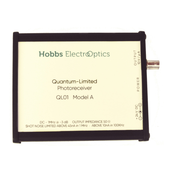
Section 3: Photos Photos Figure 3.1: Top view of the instrument Figure 3.2: Bottom view showing 1-3/4” mounting flange with 1/4”-20 or M6 threaded mounting hole QL01... - Page 10 Section 3: Photos Figure 3.3: End view showing power connector, power indicator LED, and output BNC QL01...
-
Page 11: Quick Guide To Using The Ql01
Section 4: Quick Guide To Using The QL01 Quick Guide To Using The QL01 The Hobbs ElectroOptics QL01 is designed to be very simple to use: basically you put it in your optical system, connect the power supply and output cable, tweak the alignment, and your low-level measurement troubles just got a lot less troublesome. - Page 12 Section 4: Quick Guide To Using The QL01 bright laser beam were inadvertently to hit the photodiode, which shouldn’t happen in a low-light measurement system. Short pulses with high peak power and very low duty cycles can also cause problems. You can check this by using a few ND 0.3 or 0.5 filters in different combinations.
-
Page 13: Theory Of Operation
Section 5: Theory of Operation Theory of Operation In this section we discuss the problems of low noise photoreceiver design, with specific ref- erence to the QL01. Some of the figures are from Building Electro-Optical Systems: Making It All Work [1], where you’ll find lots more on this and many other topics. For any missing background on circuit design and low noise design in particular, see The Art of Electronics by Horowitz and Hill [2], especially Chapter 8. - Page 14 Section 5: Theory of Operation impedance Z is R and C in parallel, (5.1) 1 + j 2πf C and the output voltage is I photo The output voltage rolls off by 3 dB where the real and imaginary terms become equal, i.e.
-
Page 15: Shot Noise
Section 5: Theory of Operation All amplifiers have some amount of noise in both voltage and current. In the photocurrent range of the QL01, we’d pick a FET-input amplifier, whose current noise is very small. Its voltage noise density e will be reasonably constant above about 1 kHz, so as the signal NAmp rolls off... - Page 16 Section 5: Theory of Operation density is (5.6) Nshot photo where e is the charge of the electron, about 1.602·10 coulombs. (This formula is not √ mysterious— it’s just N converted to a current and quoted in the frequency domain.) Measurements where the noise of the photocurrent dominates are said to be in the shot noise limit.
-
Page 17: Transimpedance Amplifiers
Section 5: Theory of Operation Transimpedance Amplifiers We may observe that the signal swing across the photodiode capacitance is the root of the problem—if there’s no swing, there’s no capacitive current. Thus if we apply feedback around A1 to wiggle the far end of R so as to keep the photodiode end still, all of the photocurrent has to flow through R , and ideally there’s no rolloff. -
Page 18: Bootstraps
Section 5: Theory of Operation Figure 5.3: Conceptual schematic of a bootstrapped transimpedance amplifier advanced design minimizes this effect, it cannot be entirely avoided, as you can see in Figures and 6.3. Bootstraps Another approach, shown in Figure 5.3, is to use an auxiliary amplifier A2 to apply feedback to the ground end of the photodiode to make it follow the signal end. - Page 19 Section 5: Theory of Operation 20 dB improvement over the op amp of Figure 5.2. The QL01’s design uses two main features to achieve its high performance: reverse biasing the photodiode, which reduces its capacitance by more than a factor of 5, and a proprietary bootstrap circuit with sub-nanovolt noise density and a gain of more than 0.999 over a wide bandwidth, reducing the effect of capacitance by more than a factor of 1000.
-
Page 20: Performance Verification
Section 6: Performance Verification Performance Verification This section presents measured noise and transient response data for the QL01-A and -B along with a discussion of how to verify this performance yourself. Pulse Response and Bandwidth The easiest way to verify the bandwidth is to measure the response to a square pulse. The transient data plotted below were taken using a Highland Technology P400 digital delay generator driving a red LED via an RC filter with a 100 ns time constant (2 nF in parallel with the generator’s 50 Ω... - Page 21 Section 6: Performance Verification to obtain a corresponding benefit. (Be sure to use a filter that is not a short circuit to ground at DC—highpass and bandpass filters sometimes are.) Noise floor measurements with spectrum analyzers and some digital scope FFTs may require correction.
-
Page 22: Finding The Shot Noise Limit
Section 6: Performance Verification widths will be larger than 1/t by some unknown amount and so will require additional correction. The dynamic range of an oscilloscope digitizer is quite limited—only 6 to 8 bits’ worth in most cases—so it is important to eliminate interfering signals such as room lights and to use the most sensitive input range that avoids clipping the noise peaks. -
Page 23: Transient Response (Model A And B)
Section 6: Performance Verification Transient Response (Model A and B) 391 ns 0 s 250 ns 500 ns 750 ns 1 s 1.25 s 1.5 s 1.75 s 2 s Time 408 ns 0 s 250 ns 500 ns 750 ns 1 s 1.25 s 1.5 s 1.75 s 2 s Time Figure 6.1: Step response of the QL01. - Page 24 Section 6: Performance Verification to get back to volts. The squared noise voltage in the ith bin is 0.1PSD (dBV @ 1 Hz) ) = B 10 (6.2) The ith bin covers the frequency interval [iB, (i + 1)B), so we can sum straightforwardly /B 1 (6.3) Ndark...
- Page 25 Section 6: Performance Verification noise, subtract the dark sum from the light sum to get the sum of the photocurrent noise contribution, and compare that to the dark sum. That will lump in all sources of noise on the photocurrent, including spurious modulation and source noise as well as shot noise. QL01...
-
Page 26: Model A Noise Floor
Section 6: Performance Verification Model A Noise Floor −114 Output Noise at 50nA 50nA Shot Noise −116 −118 −120 −122 −124 −126 10 nA 10M Johnson Noise (300K) 20 nA −128 50 nA Dark Noise −130 0 Hz 200 kHz 400 kHz 600 kHz 800 kHz... -
Page 27: Model B Noise Floor
Section 6: Performance Verification Model B Noise Floor Output Noise at 50nA 50nA Shot Noise −114 −116 −118 −120 −122 −124 −126 10 nA 10M Johnson Noise (300K) 20 nA −128 50 nA Dark Noise −130 0 Hz 200 kHz 400 kHz 600 kHz 800 kHz... -
Page 28: References
References [1] Philip C. D. Hobbs. Building Electro-Optical Systems: Making It all Work, Second Ed. Wiley Series in Pure and Applied Optics. Wiley, 2009. isbn: 9780470402290. url: http: //www.wiley.com/WileyCDA/WileyTitle/productCd-0470402296.html. [2] Paul Horowitz and Winfield Hill. The Art of Electronics, Third Ed. Cambridge, 2015. isbn: 9780521809269. -
Page 29: Table Of Symbols
Table of Symbols EMI Electromagnetic interference. FFT Fast Fourier transform (to transform from time to frequency and back). Ms/s Megasamples per second. NEP Noise equivalent (optical) power. OEM Original equipment manufacturer. RMS Root-mean-square. SNR Signal-to-noise ratio (signal power / noise power). TIA Transimpedance amplifier. - Page 30 Hobbs ElectroOptics 160 North State Road, Suite 203 http://hobbs-eo.com Briarcliff Manor, NY 10510 info@hobbs-eo.com (914) 236-3005 QL01...
Need help?
Do you have a question about the QL01 Series and is the answer not in the manual?
Questions and answers