Table of Contents
Advertisement
Quick Links
Resistance Welding Solutions
INSTALLATION, OPERATING AND MAINTENANCE MANUAL
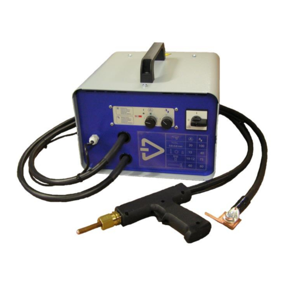
RESISTANCE WELDING POWER SOURCE
FAST SPOTTER 3.5 E & 5.0
Westermans International Ltd
Unit 4 Midland Distribution Centre
Markfield Road, Groby, Leicestershire
LE6 0FS
Tel+44(0)116 2696941
welding@westermans.com www.westermans.com
Advertisement
Table of Contents

Subscribe to Our Youtube Channel
Summary of Contents for Westermans International FAST SPOTTER 3.5
- Page 1 Resistance Welding Solutions INSTALLATION, OPERATING AND MAINTENANCE MANUAL RESISTANCE WELDING POWER SOURCE FAST SPOTTER 3.5 E & 5.0 Westermans International Ltd Unit 4 Midland Distribution Centre Markfield Road, Groby, Leicestershire LE6 0FS Tel+44(0)116 2696941 welding@westermans.com www.westermans.com...
- Page 2 Resistance Welding Solutions INDEX GENERAL INSTRUCTIONS Manufacturer and welding machine identification data General safety warnings Prevention measures to be taken by the user Technical data Intended and non intended use Description of the product and how it works INSTALLATION INSTRUCTIONS Environmental conditions Energy requirement Connection to the energy sources...
-
Page 3: General Instructions
Resistance Welding Solutions GENERAL INSTRUCTIONS MANUFACTURER AND WELDING MACHINE IDENTIFICATION DATA Manufacturer data P.E.I.-POINT SRL Welding machine data Resistance type welding machine; see the data plate on the machine and the certificate of conformity attached to this manual for the model, serial number and year of construction. -
Page 4: General Safety Warnings
Resistance Welding Solutions GENERAL SAFETY WARNINGS THE FAILURE TO OBSERVE THESE WARNINGS AND/OR ANY MODIFICATION OF OR TAMPERING WITH THE WELDING MACHINE WILL RELEASE P.E.I.-POINT SRL FROM ANY LIABILITIES IN THE CASE OF ACCIDENTS TO PEOPLE OR DAMAGE TO THINGS AND/OR TO THE WELDING MACHINE ITSELF. Before turning the welding machine on it is essential that the user knows how to carry out all the operations described in this manual. -
Page 5: Technical Data
Resistance Welding Solutions PREVENTION MEASURES TO BE TAKEN BY THE USER ▪ We recommend wearing safety glasses. The user must observe the safety instructions given on the welding machine. ▪ ▪ Personal protection gear must comply with and be certified by current standards. Signs must be placed in the vicinity of the machine relative to the risks that call for personal protection gear. - Page 6 Resistance Welding Solutions DESCRIPTION OF THE PRODUCT AND HOW IT WORKS P.E.I.-POINT SRL spot welders belong to the family of resistance type welding machines. By this we mean autogenous welding obtained by pressure, without using weld material, using the thermal effect of electricity flowing through the components to be welded (Joule effect) for heating.
-
Page 7: Installation Instructions
Resistance Welding Solutions INSTALLATION INSTRUCTIONS ENVIRONMENTAL CONDITIONS Operating clearances The machine must be positioned to ensure working and maintenance clearances and for any emergency situations that may arise. For this reason we recommend leaving a clearance of about 1 metre all around the machine. Environmental characteristics The place where the machine is going to be used must be suitably illuminated for both production and maintenance, free from dust, acids, corrosive substances or gases, with temperatures ranging between +5°C and +40°C. - Page 8 Resistance Welding Solutions DATA ON TRANSPORTING, STORAGE AND ASSEMBLY Shipping Make sure that the means used to transport the welding machine is strong enough to withstand its weight. Pay attention to the air connections and projecting parts to avoid any damage being done. The weights of the different models are given in the technical data.
-
Page 9: Wiring Diagrams
Resistance Welding Solutions WIRING DIAGRAMS C:\Users\Owner\Desktop\Pmanual FAST SPOTTER 35 and 5.0 S1 and PX1600.doc - 9 -... -
Page 10: Instructions For The Operator
Resistance Welding Solutions INSTRUCTIONS FOR THE OPERATOR DESCRIPTION OF THE FUNCTIONS To weld, the operator can either press the green button on the gun or use the lever switch on the studder gun. Squeeze time tests can be run without welding by pressing the black push button. When the welding control unit receives consent to start the cycle it performs the welding sequence according to the parameters set on it. - Page 11 Resistance Welding Solutions Current Welding current influences the strength of the spot as does weld time but the influence is much stronger. This means that current is the variable factor and must be adjusted with maximum attention. To find the optimum welding current you have make several attempts on some sample pieces, starting from a low value (10) and gradually increasing up to a satisfactory value (max.
- Page 12 Resistance Welding Solutions DESCRIPTION OF THE WELDING CONTROL UNIT DESCRIPTION OF THE SYNOPTIC PANEL The synoptic panel is divided in two parts. The top shows the graphical symbols of the available functions as well as the two LEDs signalling the power on and the welding time. The bottom includes two potentiometer for time and power adjustment. DESCRIPTION OF THE FUNCTIONS S1 is a timer that controls the welding cycle .
- Page 13 Resistance Welding Solutions DESCRIPTION OF THE WELDING CONTROL UNIT PX1600 WELDING CONTROL DESCRIPTION OF THE SYNOPTIC PANEL The synoptic panel is divided in two parts. The top shows the graphical symbols of the functions available as well as the LED s signalling the function selected.
-
Page 14: Description Of The Functions
Resistance Welding Solutions DESCRIPTION OF THE FUNCTIONS PX1600 is a timer that controls the welding cycle . A mains period is the timer’s unit of time, corresponding to 1/50 of a second (50Hz). If, for instance, a squeeze time of 50 periods is set, time will be equal to 1 second. Squeeze time (0-99 periods): it is the time needed by the welding machine’s electrodes to come into contact with the piece to be welded and to exert the welding pressure Melted material will squirt if this time is too short. - Page 15 Resistance Welding Solutions PROGRAMMING When the control is not carrying out a welding cycle it can be used to programme or modify welding parameters. Simply press the key to select the parameters of the welding cycle wanted. The illuminated green LED under the graphical symbol highlights the function selected. The SET VALUE display shows the value of the function selected.
- Page 16 Resistance Welding Solutions DESCRIPTION OF CONTROL CONNECTIONS name Description PRG1 (in) Start cycle with time-current 1 (active when low) PRG2* (in) Start cycle with time-current 2 (active when low) SPOT (in) Start cycle wioth time-current 2 without solenoid valve EV1 (active whern low) WELD (in) Welding time enable (active when low)
- Page 17 Resistance Welding Solutions 3.8.1 TROUBLESHOOTING AND A GUIDE TO ELIMINATING PROBLEMS IN THE WELDING CYCLE PROBLEM CAUSE REMEDY • No electricity • Check mains voltage and soundness of The control unit does not turn when the main switch has been turned on. •...
-
Page 18: Maintenance Instructions
Resistance Welding Solutions MAINTENANCE INSTRUCTIONS MAINTENANCE INFORMATION Maintenance personnel must be qualified, know the welding machine and work without modifying the safety of the product. The maintenance person must also respect the general accident prevention rules and regulations. Small maintenance jobs Use a fine grain file to keep the electrode tips free from ferrous waste and from the small craters that form. -
Page 19: Spare Parts
Resistance Welding Solutions SPARE PARTS Here is a list of the basic spare parts for those parts subject to wear and tear and for the machine’s safety devices. item code description Cs150 Welding control S1 without SCR thyristor module ME341 Main switch 16A 2 POLI P0160002R001 Item Code... -
Page 20: Technical Assistance
Resistance Welding Solutions SPARE PARTS item code description TR084 Welding transformer FAST SPOTTER 3,5 E – 400V ME050 Thyristor module SCR SKKT 92/16E ME178 Thermostat 70° L01.070.05.300 TECHNICAL ASSISTANCE If the problem you have with the welding machine is not mentioned in the TROUBLESHOOTING table then contact an authorised dealer. C:\Users\Owner\Desktop\Pmanual FAST SPOTTER 35 and 5.0 S1 and PX1600.doc - 20 -... - Page 21 Persona autorizada para constituir la edición técnica: Il legale rappresentante: Silvano Marzaro The legal representative: Der Gesetzliche Vertreter: Le représentant légal : Representante Legal: Westermans International Ltd Unit 4 Midland Distribution Centre Markfield Road, Groby, Leicestershire LE6 0FS Tel+44(0)116 2696941 welding@westermans.com www.westermans.com...
Need help?
Do you have a question about the FAST SPOTTER 3.5 and is the answer not in the manual?
Questions and answers