
Summary of Contents for e-Yantra Team eYFi-Mega
- Page 1 Hardware Manual for eYFi-Mega Development Board Produced by: e-Yantra Team https://e-yantra.org/products/eyfi-mega Version: 0.1 Dated: December 14, 2019...
- Page 2 About this Document This document is created for all developers wanting to work with the eYFi-Mega development board. It provides the detailed description and specification of the board. Revision History For revision history of this document, please refer to the Appendix A.
-
Page 3: Table Of Contents
Table of Contents 1 Board Overview Kit Contents ....... . . Quick Start . - Page 4 C Flashing Boot-loader on ESP32...
- Page 5 ..... eYFi-Mega Pinout Diagram for ATmega2560 ....
-
Page 6: Board Overview
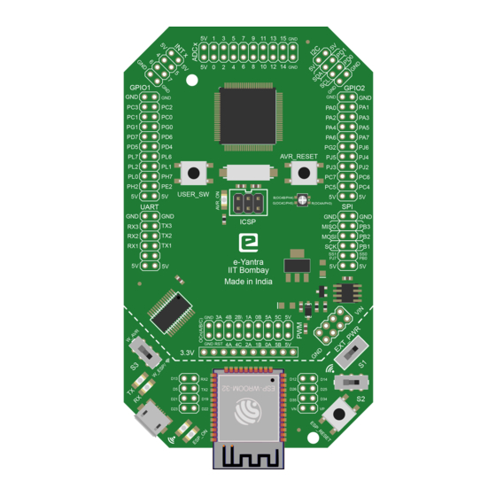
Board Overview Figure 1: eYFi-Mega development board The eYFi-Mega board provides an flexible and affordable way for users to try out new concepts and build prototype projects with the 8-bit ATmega2560 micro-controller in TQFP100 package and the 32-bit ESP32 micro-controller, choosing from the various combinations of performance, power consumption and features. -
Page 7: Kit Contents
Follow the sequence below to configure the eYFi-Mega and launch the demo software: • Connect the eYFi-Mega board to a PC with a USB micro-B plug to USB-A plug cable through USB connector to power the board. The red LEDs AVR_ON and ESP_ON should light up. -
Page 8: Features
FreeRTOS, ESP32 runs FreeRTOS out-of-the- • Arduino Programming Language Both micro-controllers can be programmed using Arduino Programming Language 1.4 Specifications Table 1 summarizes the specifications of the eYFi-Mega board. Table 1: Specifications of eYFi-Mega development board Parameter Value Board Supply Voltage 4.75 V... -
Page 9: Hardware Description
Hardware Description Figure 2: Block diagram of eYFi-Mega The eYFi-Mega board includes ATmega2560 and ESP32 micro-controllers and a range of useful peripheral features (as the block diagram in Figure 2). This chapter describes how these peripherals operate and interface to the micro-controller. -
Page 10: Atmega2560 Micro-Controller
Figure 3: Functional diagram of eYFi-Mega Table 2-1 summarizes the parts of the eYFi-Mega board with respect to the Figure 3. Table 2: Functional Diagram of eYFi-Mega Component Name Component Name ATmega2560 micro-controller PWM header INTx header EXT_PWR header ADCx header... -
Page 11: Partition Table Of On-Board Esp32 Micro-Controller
Micro-USB port or wirelessly i.e. Over-The-Air (OTA). For more information on how to update the firmware OTA, refer the Section Button - Wireless Flash in the Software Manual of eYFi-Mega development board. 2.1.2 ESP32 micro-controller ESP32-WROOM-32 is a powerful, generic Wi-Fi+BT+BLE MCU module that targets a wide variety of applications, ranging from low-power sensor networks to the most de- manding tasks, such as voice encoding, music streaming and MP3 decoding. -
Page 12: Patterns Of Wi-Fi Status Led With Various States Of The Board
Wi-Fi access point. Once a device is connected, this LED glows. It is connected to ESP32 GPIO18 pin. When you are connected to your eYFi-Mega over a Wi-Fi link, it is important to know the different states in which your board is. These states are indicated by this LED. - Page 13 One can also use this switch for debugging purposes by printing data on the Wired Serial Monitor. For more information on Wired Serial Monitor, refer to the Section Button - Wired Serial Monitor in the Software Manual of eYFi-Mega development board.
-
Page 14: Function Of Switches S1, S2 And S3
2.1.1. The ICSP connector pins are shown in Figure 4. Note: If you use ISP programmer with the eYFi-Mega board and try to load .hex file on to ATmega2560 then boot section code will get erased and the ATmega2560 will no longer be programmable via wired connection or wirelessly. -
Page 16: Adcx Header
2.1.8 GPIO2 header This is another header which is also a group of pins of ATmega2560 that can be used as General Purpose Input Output (GPIO) to connect any input or output peripheral de- vices. Apart from using these pins as GPIO, they also have certain alternative functions, the details of the same is shown in Figure 4. -
Page 17: Spi Header
protocol in the micro-controller. There are four UART modules from UART3 to UART0 in ATmega2560. The TX and RX pins of UART3:1 are present on this header. The TX and RX pins of UART0 is not made available on the board. Apart from using these pins as TX and RX pins of UART module, they also have certain alternative functions, the details of the same is shown in Figure 4. -
Page 18: Micro-Usb Connector
Figure 5. This header also has Transmit (TX) and Receive (RX) Data pins of UART2 of ESP32. 2.1.16 Micro-USB connector This is a Micro-USB port where a USB micro-B plug to USB-A plug cable can be con- nected to the PC. It can be used to flash the firmware on ATmega2560 or ESP32 via wired connection. -
Page 20: Power Management
ESP32 and will reduce its Wi-Fi signal strength. 3.3 EXT_PWR header This header is a group of pins where the eYFi-Mega board can be powered by an External DC Supply. These pins are divide into VIN and GND each having four pins. The positive terminal of External DC Supply should be connected to any of the four VIN pins and the negative terminal should be connected to any of the four GND pins. -
Page 21: References
References In addition to this document, the following references will be helpful: 1. ATmega2560 datasheet, available at https://ww1.microchip.com/downloads/ en/devicedoc/atmel-2549-8-bit-avr-microcontroller-atmega640-1280- 1281-2560-2561_datasheet.pdf 2. ESP32-WROOM32 datasheet, available at https://www.espressif.com/sites/ default/files/documentation/esp32-wroom-32_datasheet_en.pdf 3. Espressif IoT Development Framework (ESP-IDF) Programming Guide, available https://docs.espressif.com/projects/esp-idf/en/stable/index.html 4. I2C Protocol explained (a) by Sparkfun: https://learn.sparkfun.com/tutorials/i2c (b) by Texas Instruments (TI) -
Page 22: Appendices
Appendices Revision History Table 7: Revision History of the document Date Version Release notes December 14, 2019 v0.1 First release of the document... -
Page 23: B Flashing Boot-Loader On Atmega2560
If the LED color is Green, this means that everything is working fine and you can proceed with the next step. But, if the LED color is Orange or Red, this means that the connections between the Atmel AVRISP mkII and eYFi-Mega board is weak. -
Page 24: Device Programming Dialog Box In Atmel Studio
6. Open the Atmel Studio 7 software. Select the option Device Programming or use the shortcut Ctrl + Shift + P. A dialog box will open as shown in Figure 6. 7. Under Tool option, select AVRISP mkII. 8. Under Device option, select ATmega2560. 9. -
Page 25: All Ok Message After Programming The Fuses
20. Once the programming is complete, you will get the message: Verifying Flash..OK. The LED color on Atmel AVRISP mkII will turn to Orange and will blink continu- ously. 21. Congrats! Your eYFi-Mega board is updated with the Boot-loader firmware of AT- mega2560. - Page 26 1. To upload the Boot-loader firmware of ESP32: refer the Section Flashing eYFi- Mega ESP32 Bootloader in the Software Manual of eYFi-Mega development board. 2. To upload the Partition Table of ESP32: refer the Section Flashing eYFi-Mega ESP32 Partition Table in the Software Manual of eYFi-Mega development board.
Need help?
Do you have a question about the eYFi-Mega and is the answer not in the manual?
Questions and answers