
Related Manuals for SILICON SENSING DMU30

Summary of Contents for SILICON SENSING DMU30
- Page 1 DMU30 Evaluation Kit User Manual DMU30-00-0100-910 DMU30-00-0100-910 Page 1 Issue 1, June 2015 DCR 710009247...
- Page 2 THE EVALUATION KIT DESCRIBED IN THIS DOCUMENT IS A DEVELOPMENT TOOL AND AS SUCH IS PROVIDED SOLELY FOR THE EVALUATION AND ASSESSMENT BY THE PURCHASER OF THE SUITABILITY OF THE SILICON SENSING SYSTEMS LIMITED (SSSL) RANGE OF INERTIAL SENSORS WITHIN THE PURCHASER’S APPLICATION. THEY ARE NOT TO BE USED EITHER AS AN INTEGRAL OR DISCRETE PART OR COMPONENT WITHIN ANY PURCHASER APPLICATION OR PRODUCT.
- Page 3 Entitled: DMU30 Evaluation Kit User Manual This is an unpublished work created in 2015, any copyright in which vests in Silicon Sensing Systems Limited. All rights reserved. The information contained in this document is proprietary to Silicon Sensing Systems Limited unless stated otherwise and is made available in confidence;...
-
Page 4: Table Of Contents
5.4.5 Settings Tab ......................... 28 5.4.6 Changing the MEV 485i Driver Settings ..............29 Using the DMU30 without the Evaluation Kit ..........32 Sensor Sampling and Synchronisation ..................34 DMU30 Electrical Connections ..............35 Installation ....................... 35 Software Updates ................... 36 Contact Details .................... - Page 5 Figure 15: Settings Page ..........................28 Figure 16: DMU30 Architecture ........................32 Figure 17: Connection to a Host System ....................33 Figure 18: Interface Cable 630567-0940 ....................35 Figure 19: Pin numbering of the DMU30 socket..................35 Figure 20: DMU30 Installation ........................36 DMU30-00-0100-910 Page 5...
- Page 6 Parallel port interface Mega Bytes milliseconds Original Equipment Manufacturer Personal Computer Printed Circuit Board Random Access Memory Ring Laser Gyroscope Receive Service Pack Transmit Universal Serial Bus Velocity Page 6 DMU30-00-0100-910 DCR 710009247 Issue 1, June 2015...
-
Page 7: Introduction
DMU10 to Power supply adapters DMU30 power supply MEV Cable Figure 1: DMU30 Evaluation Kit 2 System Requirements The DMU30 Evaluation Kit requires a PC with a USB port. The requirements for the PC are as follows: ® ® ®... -
Page 8: Potential Restrictions And Issues
USB to serial devices that are using this driver. If the PC used to run the DMU30 Utility software will be used for other applications that use this driver then it may be necessary to undo (or change) the settings described in section 5.4.6. -
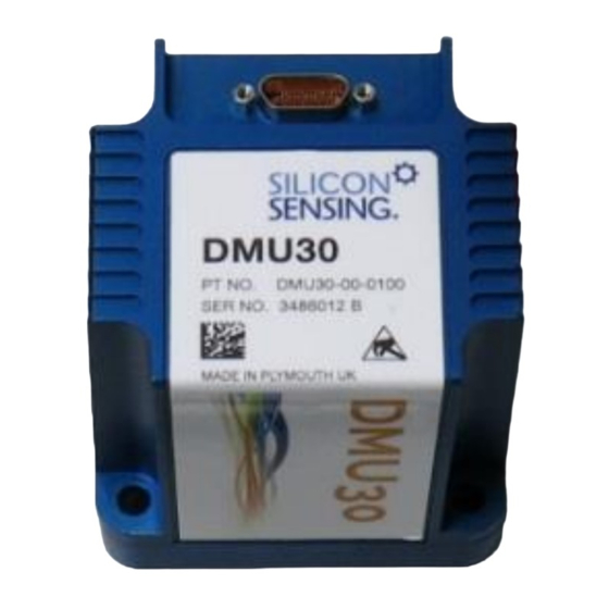
Page 9: Figure 2: Dmu30
Figure 2: DMU30 DMU30-00-0100-910 Page 9 Issue 1, June 2015 DCR 710009247... -
Page 10: Mev Rs485I To Usb Converter And Cd
This User Manual DMU30 Brochure 4.4 Interface Cables Two cables are included in the kit: 1. DMU30 to MEV Cable (Part Number 630567-0940) 2. MEV to PC USB 2.0 Cable. Page 10 DMU30-00-0100-910 DCR 710009247 Issue 1, June 2015... -
Page 11: Getting Started
Note that in Windows 7, this icon can disappear into the hidden icon box when the dialog disappears. Installing device driver icon Windows 7 hidden icons box 4. When the dialog shown below appears, click Skip obtaining driver software from Windows Update. DMU30-00-0100-910 Page 11 Issue 1, June 2015 DCR 710009247... - Page 12 6. The following dialog should then appear and you must wait (do not click Close because the installation program has not completed yet): 7. The installation program should then locate the previously installed drivers and you should eventually see the following dialog: Page 12 DMU30-00-0100-910 DCR 710009247 Issue 1, June 2015...
-
Page 13: Mev Installation Troubleshooting
COM ports. These devices will disappear when the USB cable is removed but should re-appear when it is re-inserted. These same COM ports will appear in the DMU30 Utility serial port drop down list, enabling the application to connect to different MEV devices. -
Page 14: Installing The Data Logging Software
Additional information may be also available on the MEV website at http://www.mev.co.uk 5.3 Installing the Data Logging Software The data logging software is included on the USB Memory Stick within the DMU30 Evaluation Kit. This software should work on all supported versions of Windows including XP. - Page 15 You may see the following message displayed because the software is proprietary to Silicon Sensing Systems Ltd and has not been registered with Microsoft. 6. Click Install to install the data logging software. DMU30-00-0100-910...
-
Page 16: Installation Troubleshooting
5.4 Using the Software 5.4.1 Starting the Application Go to Start | All Programs | Silicon Sensing and select DMUXX to launch the application. Note: In Windows 8, the installation will create a DMU30 icon in the Start menu. To use the application, the interface cables described in section 4.4 must be used to connect together the PC, MEV and DMU30. -
Page 17: Main Window
Use ‘maximize’ Example of Main Tab Page containing its button to run in Common Menu Controls Main Tab Options own tab pages full screen mode Figure 4: Software Application Main Window DMU30-00-0100-910 Page 17 Issue 1, June 2015 DCR 710009247... -
Page 18: Figure 5: Main Controls
5.4.2.1 Common Controls Connect / Disconnect Displays the number of DMU30 Selects the PC COM button opens the output messages lost in the port used to currently selected PC current session. Clicking this communicate with the COM port. control will reset the count to zero. -
Page 19: Display Tab
5.4.3 Display Tab The Display tab displays the DMU30 output data in real-time using level meters and a chart recorder. The “Connect / Disconnect” button must be pressed to connect the DMU30 in order to display DMU30 data output. 5.4.3.1 Level Meters Display... -
Page 20: Figure 8 Chart Recorder Overview
The filter allows for multiple strings to be added using a “,” (comma) separator. So for example “Accel,Rate” would select all the traces containing either “Accel” or “Rate” in their title. Note that spaces are significant in the string fragments. Page 20 DMU30-00-0100-910 DCR 710009247 Issue 1, June 2015... - Page 21 (“Axis X Rate”) have been set. In this way it is therefore possible to identify which individual sample values have BIT flags associated with them. For convenience, sample values with associated BIT flags can be marked (using a white circle) by selecting “Show point marks”. DMU30-00-0100-910 Page 21 Issue 1, June 2015 DCR 710009247...
-
Page 22: Figure 9 Marking Sample Points With Associated Bit Errors
Selecting “Annotated” cursors will display sample data inside a box with trace title annotations against the data values. Otherwise the data values will be displayed at the far right of the window. Page 22 DMU30-00-0100-910 DCR 710009247 Issue 1, June 2015... -
Page 23: Logging Tab
For data logging, you must first connect the application to a MEV USB Serial Port as described in section 5.4.2.1. The Logging tab contains two tabs: Log to memory Log to disk DMU30-00-0100-910 Page 23 Issue 1, June 2015 DCR 710009247... -
Page 24: Figure 11: Logging Tab Overview
Indicates the Displays the completion Select this tab to log Select this tab to log progress of the percentage for the DMU30 output data to DMU30 output data current logging current logging session.. to memory. Data is disk. session. -
Page 25: Table 1: Operational Message Data Output Descriptions
This option should be used for short logging sessions where it is useful to view the data on- screen. Logged data can also be saved to disk in CSV format. The LoggingMinAvailableMemorySpaceBytes setting (see Table 2) enables the user to control the remaining memory space limit. DMU30-00-0100-910 Page 25 Issue 1, June 2015 DCR 710009247... -
Page 26: Figure 12: Log To Memory Tab
Clears the Displays captured DMU30 Indicates the available, remaining memory space. current logging output data. When this value falls below the value set for the “LoggingMinAvailableMemorySpaceBytes” session from Data columns can be memory. sorted by clicking the setting, logging will stop. -
Page 27: Figure 13: Log To Disk Tab
The LoggingMinAvailableDriveSpaceBytes setting (section 5.4.5) allows the user to control the remaining drive space limit. Indicates the available, remaining drive space. Displays DMU30 output When this value falls below the value set for the data in real-time using LoggingMinAvailableDriveSpaceBytes setting, level meters. -
Page 28: Settings Tab
Figure 14: Log files in the default log file directory 5.4.5 Settings Tab The Settings tab displays application user settings for editing. If you require a setting to become permanent (i.e. persist between DMU30 Utility re-starts) click Save settings. Figure 15: Settings Page Page 28... -
Page 29: Changing The Mev 485I Driver Settings
Please do not attempt to change any parameters not listed in Table 2. Changes may result in non-functioning software. 5.4.6 Changing the MEV 485i Driver Settings To perform correctly the DMU30 utility software requires non-default MEV 485i driver settings. The software will attempt to change them if it detects that they are incorrect. - Page 30 In Windows 7, this can be accessed using Start / Control Panel / Hardware and Sound / Device Manager. 2. Open Ports (COM & LPT) 3. Double click the port that requires changing (the COM port that the DMU30 Utility will connect to) Page 30...
- Page 31 Administrator rights before continuing with this procedure. Otherwise, change the Receive (Bytes) value to 2240 and the Latency Timer (msec) value to 1 (as shown below). 6. Click OK to save these settings. DMU30-00-0100-910 Page 31 Issue 1, June 2015 DCR 710009247...
-
Page 32: Using The Dmu30 Without The Evaluation Kit
6 Using the DMU30 without the Evaluation Kit The information in this section is provided to enable the user to use the DMU30 with alternative logging equipment. Figure 13 shows the internal architecture for DMU30. Figure 16: DMU30 Architecture Table 3 shows the connector pin out for DMU30. -
Page 33: Table 4: Operational Message Data Output Descriptions
A typical connection to a host system is shown in Figure 17. Note that some connections are not essential for correct operation. Figure 17: Connection to a Host System Table 4 describes the format of the data output message for DMU30. Item Word... -
Page 34: Sensor Sampling And Synchronisation
6.1 Sensor Sampling and Synchronisation When the DMU30 Evaluation Kit is not used, it is possible to make use of the ‘Sync Pulse’ output from the DMU30. The Inertial Sensors within DMU30 are all sampled at 1000 Hz. The ‘Sync Pulse’ on the connector is set HIGH at the start of the sampling and returned to LOW when the last Inertial Sensor is sampled. -
Page 35: Dmu30 Electrical Connections
7 DMU30 Electrical Connections The interface cable shown in Figure 18 enables the DMU30 to be connected directly to the MEV interface allowing the application to be used immediately. Figure 18: Interface Cable 630567-0940 Should the user wish to connect to the DMU30 to a separate power supply and/or logging software, a 15-way micro D-type connector will need to be purchased (manufacturer part number MWDM2L-15P-6E5-18), as it is not included in the evaluation kit. -
Page 36: Software Updates
Figure 20: DMU30 Installation 9 Software Updates If there has been an update to the software supporting the DMU30 Evaluation Kit, it can be downloaded from the ‘Software’ section of the download library at: http://www.siliconsensing.com/information-centre/downloads-library/ 10 Contact Details If you require any additional information about the DMU30 Evaluation Kit or any other products please contact Silicon Sensing via: www.siliconsensing.com... - Page 37 This is the final page of this document DMU30-00-0100-910 Page 37 Issue 1, June 2015 DCR 710009247...
Need help?
Do you have a question about the DMU30 and is the answer not in the manual?
Questions and answers