
Related Manuals for ED&D LT-952

Summary of Contents for ED&D LT-952
- Page 1 PRODUCT SAFETY SOLUTIONS ’ ’ LT-952 MODEL...
-
Page 2: Table Of Contents
Fuse locations: ............................16 CALIBRATION: ............................. 17 LIMITED WARRANTY: ..........................18 CONTACT INFORMATION: .......................... 18 IMPORTANT! READ THE ENTIRE MANUAL BEFORE USING THE LT-952 Page 1 of 19 © 2012 Educated Design & Development, Inc. All rights reserved. Rev B: February, 2012... -
Page 3: M O D E L L T
IMPORTANT INSTRUCTIONS - RETAIN THESE INSTRUCTIONS FOR FUTURE REFERENCE INTRODUCTION: Thank you for choosing the ED&D LT-952. With proper use and care it will give many years of accurate and reliable service. Upon receiving the unit please check for obvious physical damage to the packaging material and the instrument itself. -
Page 4: Understanding Leakage Current
PRODUCT SAFETY SOLUTIONS The LT-952 is designed to test any single-phase product rated 100-120 or 200-240 Volts that requires 15 Amps or less current. True 15 Amp open neutral, open ground, and line polarity (forward/reverse) test conditions. 120V front panel receptacle provides quick access for testing 120V products. -
Page 5: Before Using
PRODUCT SAFETY SOLUTIONS Understanding Leakage Current: (Continued) etc.), it may be appropriate to measure the leakage current in the grounding conductor or from any exposed surfaces to ground. (Refer to “Field Testing Grounded Products”, Chapter 2, for additional details.) During this test, the unit is energized and any switches within the product controlling primary power (and likely to be operated in normal use) are opened and closed in all possible combinations. -
Page 6: Product Components
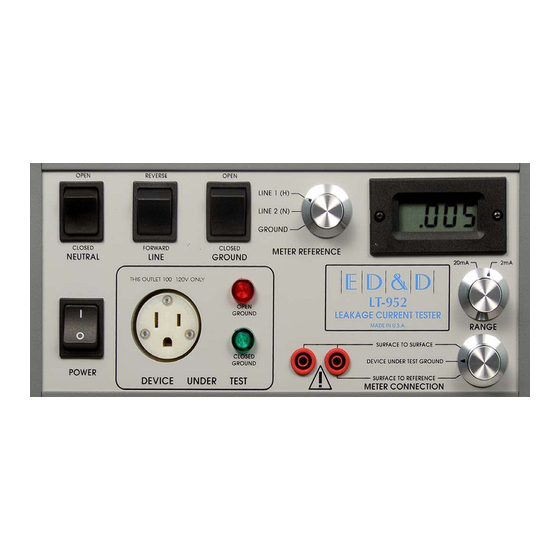
PRODUCT SAFETY SOLUTIONS PRODUCT COMPONENTS: I. Figure 1 - Front Panel A. Neutral Open / Closed Switch B. Line Forward / Reverse Switch C. Ground Open / Closed Switch D. LCD Display E. Power On / Off Switch F. D.U.T. (Device Under Test) Receptacle G. - Page 7 E. POWER SWITCH: This switch controls power to the internal circuitry of the LT-952 only. When the switch is ON, the meter display should be visible and the green Ground Closed lamp should be lit. For safety, the LT-952 is designed to disable both the front and rear panel outlets when the power switch is OFF.
- Page 8 – Hazardous Voltage exists at the banana jacks when the Meter Reference Switch is set to Line and the LT-952 is set for 115 Volt operation. Hazardous Voltage also exits at the banana jacks when the Meter Reference Switch is set to Line or Neutral and the LT-952 is set for 230 Volt operation.
- Page 9 WARNING! – Any external equipment connected to these jacks must be electrically isolated from the AC line. Failure to do so can result in damage to the LT-952 or the connected equipment. CAUTION! - The line 1 (Hot) conductor of the rear panel D.U.T. output connector is energized at all times when the LT-952 is connected to a power source! A.
-
Page 10: Product Specifications
Between two exposed surfaces Frequency Response of the Meter: The LT-952 measures cumulative leakage current from all frequencies up to and including 1MHz. Page 9 of 19 © 2012 Educated Design & Development, Inc. All rights reserved. Rev B: February, 2012... -
Page 11: Operating Instructions
5. Connect the product under test to the front panel receptacle. Make sure that the product under test’s power switch is ON. 6. Turn the Power switch of the LT-952 to ON. Observe that the leakage indicated on the LT-952 is ZERO. This is normal as the leakage current is flowing through the still connected product ground. - Page 12 6. Set the Power switch of the LT-952 to ON. Observe that the leakage indicated on the LT-952 is ZERO. This is normal as the leakage current is flowing through the still connected product ground. 7. Connect a test lead from the right front panel banana jack on the LT-952 to the surface to be tested on the product.
- Page 13 5. Connect the product under test to the front panel receptacle. Make sure that the product under test’s power switch is ON. 6. Connect the test leads from the front panel banana jacks on the LT-952 to the two surfaces to be tested on the product.
-
Page 14: Theory Of Operation
THAT CAN CAUSE THE METER FUSE TO BLOW. THEORY OF OPERATION: This section of the manual contains a description of the circuitry used in the LT-952. During this discussion, please refer to the Block Diagram located following this section. The LT-952 is composed of 3 major sections. The first is the high current handling switching section. The second is the meter measurement section, and the third is the low Voltage power supply. - Page 15 A power relay, a DPST type, is used to disconnect the front panel 120 Volt outlet when the rear panel Voltage selector is set to 230 Volt operation. If 230 Volts is inadvertently applied to the LT-952 while the Voltage selector is set to 115, the line fuse is designed to open which will cause the relay contacts to open.
-
Page 16: Troubleshooting
Problem The meter display is blank and the Ground Closed indicator does not light when the LT-952 is turned on. Solution: Check to make sure that the LT-952 is receiving power and that the Voltage Selector switch is in the proper position. Check the Line Fuse on the LT-952. -
Page 17: Reference Standards
TROUBLESHOOTING: (continued) designed to blow if the LT-952 is connected to 230 Volts and the Voltage Selector switch is set to 115. If the Voltage Selector switch is set to the proper position and the fuse still blows, then the LT-952 has been damaged and should be returned to E.D.&D. -
Page 18: Calibration
The recommended calibration intervals are as follows: 6 Months - If the LT-952 is being used in an environment where it is subject to vibration and frequent changes in temperature (i.e. Field Testing). 12 Months - If the LT-952 is being used in a laboratory or production setting with a controlled environment. -
Page 19: Limited Warranty
Educated Design & Development, Inc. (“ED&D”) hereby warrants to the original purchaser of any new ED&D Model LT-952 Leakage Current Tester that the device shall be free from defect in material and/or workmanship. This warranty shall extend for a period of 1 year (365 days) from the date of purchase.
Need help?
Do you have a question about the LT-952 and is the answer not in the manual?
Questions and answers