Advertisement
Quick Links
Advertisement

Summary of Contents for DTox DTox07
- Page 1 User Guide Blue-tooth adaptor www.4dfx.com.au/DTox...
- Page 2 Nothing is infallible, and the Dtox Blue-tooth system fits into this category. DTox systems and software are under continuous development and as a result any images and screen grabs may not accurately reflect the current versions of either. Any clarification requests or suggestions about this manual can be addressed to info@4dfx.com.au...
-
Page 3: General Description
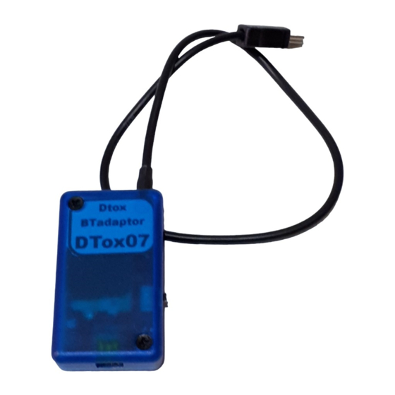
GENERAL DESCRIPTION The Dtox Blue-tooth adaptor is a replacement for the Palm Pilot programming system for P type timers (and possibly future times). The adaptor plugs into the programming port of the P type timer and programming of the timer is accomplished via the Android app, DToxconfig. -
Page 4: Operation
Amber LED will glow during charging. When fully charged the green LED will be illuminated. The unit does not have to be turned on during charging. When ready to use turn the unit on and the red status LED will begin flashing rapidly. Once connected to the Android app the green status LED will illuminate and the red indicator will flash at a much lower frequency. - Page 5 The app is free and has a ‘virtual’ timer inbuilt so you can examine/practice using its features. As with all Dtox products, its up to you to determine its suitability for your purposes and you take all responsibility for any outcomes from its use.
- Page 6 Select option B to discover any active Blue-tooth devices in range of the Android device. Only Dtox Bt adaptors will be listed. This search can take some time and when complete you will presented with a list of adaptors to choose from. You may also be asked to supply the passkey if the adaptor has not already been paired with your device.
- Page 7 SAVED LOGS: File list All files that have been saved will be listed here. Listed are the file name and description. (see the file save screen for more details) To select a file to examine or delete tap on the entry in the list (item A). Selecting option B will load the file and then enter the flight data screen from which you can then enter the graphic display.
-
Page 8: Timer Selection
TIMER SELECTION: Choose adaptor/timer Selecting option A will access the inbuilt virtual timer and allow you to examine the features of the app. No Blue-tooth connection is required and the virtual timer is reset when you exit the programming mode. You will be presented with a choice of timer to use. - Page 9 Virtual timer choice Selection is by tapping either the image or the button. All functions are available for the virtual timer as are for the real one. Once selected you will be presented with the programming options screen. Currently there is only one choice for a virtual timer.
- Page 10 Programming options Selecting option A will present the flight log of the attached timer. (see page 19) Option B will present the Status screen and provide access to the programming functions. All subsequent configuration screens have a READ and RETURN button. The READ button will refresh the data on screen by reading the timer.
- Page 11 CONFIGURATION: Status This screen displays the main current settings of the timer. No changes can be made here, if you wish to edit any settings select option A, the EDIT button, to proceed to the main edit screen. The Read button, on this and subsequent screens will refresh the display by reading the timer.
- Page 12 Main Edit Selecting option A, the MENU button, will reveal other edit options in a sub menu. Changing the times of arm release is accomplished in the ‘a’ section. You can alter either the Time or the Increment and all subsequent times will be adjusted accordingly.
- Page 13 Sub menu selection These buttons provide access to less frequently used configuration edits. Option A takes you to the altimeter edit, B to the servo position edit and C to the hardware edit. To cancel the selection option, tap anywhere on the screen.
- Page 14 Altimeter edit Section ‘a’ is the main altimeter flag, use this to enable or disable the altimeter. If any of the altimeter functions are disabled, the parameter panel will be hidden. Section ‘b’ is the recording function. The minimum flight time can be set such that any flights less than the set amount will not be recorded.
- Page 15 Servo edit This warning message is displayed to make sure you realise the possibilities of activating the power switch if there is an ESC attached to the timer as the second servo. If the system is ready and power applied, selecting the second (ESC) servo could result in motor start and a lot of damage and heartache……...
- Page 16 Servo edit The P type timer basically moves the cam servo to a predetermined positions at the programmed time. Adjustments should not be required as the timers are setup before delivery. Here is where you set the position of the servo if adjustments are required. If an ESC is attached to the timer you can also set the control pulse width at indicated times.
- Page 17 Hardware edit Only the items indicated can be edited/changed, the rest is just FYI. The text displayed for the arm positions can be edited at group ‘a’. Text is limited to 10 characters per item. Selecting item ‘b’, TP5, will include a fifth servo position labelled Arm#5, to the timing to the timing and servo edit screens.
- Page 18 Extended edit screens The above diagram illustrates the edit screen when both the 5 arm and ESC/Servo0 flags are activated. The times in the ESC group,‘D’, are edited in the same manner as the Arm Release group. Either the Time or Increment can be changed and all subsequent entries will be modified automatically.
-
Page 19: Terminal Window
TERMINAL WINDOW: The terminal window is used to directly communicate with the timer and is primarily used for debugging purposes. Commands are entered at ‘B’ and the timer response is displayed in area ‘A’ Users are not encouraged to play here, but if you must, try entering ‘d’. This will display the contents of the configuration EEPROM. - Page 20 TIMER LOGS: Flight Log screen A list of the flight logs is presented. An indication of how many flights the timer has ever recorded, and the number currently stored is displayed at the head of the list. The list contains all the flights currently stored on the timer. The Load (option C) button is inactive until an item in the list is selected.
- Page 21 Flight data screen All the records of the flight are displayed in a list, with the total number of records indicated at the top of the list. If there are more records than are displayed on the screen, the list can be scrolled. The fields of the list are as follows, the record number, the time of the altitude sample, the altitude, a timer event if applicable, the vertical speed at the time of sample and the temperature as reported by the altitude sensor.
- Page 22 Flight save screen These are the details that will be saved with the flight data. The date is pre loaded with the current day, if you wish to change the date to the actual flight date tap on the calendar icon (item A) and select the desired date. The Description field (item B) is where you enter the description of the flight, eg ‘first flight of a particular contest’.
- Page 23 Flight Plot screen Several values are displayed below the Home button (item A). The motor run time in seconds, D/T time in seconds, maximum altitude reached in meters (relative to base altitude) and the length of the recording in seconds. The flight plots time and altitude with three phases of flight indicated by different colours.
- Page 24 The screen shown above illustrates the expanded time axis and the presence of the cursor. Only the time axis can be expanded. When the time axis is expanded or contracted the final sizing may be adjusted to provide rational values for the axis marks.
Need help?
Do you have a question about the DTox07 and is the answer not in the manual?
Questions and answers