Table of Contents
Advertisement
Quick Links
Advertisement
Table of Contents

Summary of Contents for medical bees F-31 Series
- Page 1 0483 User’s Manual F-31-XXX-XX F-40-XXX-XX Battery-powered tools for large bone surgery Orthopaedic Cordless Drill / Saw System medical bees GmbH Friedrich-Woehler-Strasse 13 78576 Emmingen-Liptingen Germany Data Revision Page IFU GA-001-02 05 February 2021 1 of 88...
-
Page 2: Table Of Contents
0483 Table of Contents Table of Contents ..........................2 Introduction and product description ................... 6 General information ........................6 Intended use and indications ...................... 6 1.2.1 Handpieces, Battery (Power Pack) and attachments ..............6 1.2.2 Cleaning and maintenance accessories..................6 Contraindications ......................... - Page 3 0483 2.1.2 Drilling machine (F-31-150-00) ....................16 2.1.3 Oscillating saws Synthes AO connection (F-31-300-00; F-31-301-00) ........17 2.1.4 Oscillating saw Stryker Sawblade connection (F-31-310-00/F-31-311-00) ......18 2.1.5 Straight Oscillating saw Stryker Sawblade connection (F-40-100-00/F-40-101-00) ....19 2.1.6 Straight Oscillating saw Synthes AO connection (F-40-110-00/F-40-111-00) ......20 2.1.7 Sternum saw/ reciprocating saw with keyless chuck (F-31-601-00) .........
- Page 4 0483 Application of oscillating saws Synthes AO saw blade connection (F-31-300-00; F-31-301- 2.8.1 Start up of oscillating saws ......................43 2.8.2 Saw head positioning ........................ 43 2.8.3 Replacement of saw blades ...................... 43 2.8.4 Application of oscillating saws ....................45 2.8.5 Recommendations for handling of saw blades .................
- Page 5 0483 3.4.2 Manual pre-cleaning of the attachments / chucks ..............62 3.4.3 Mechanical cleaning ........................63 Oiling / maintenance ........................65 Packaging ............................ 65 Sterilisation ..........................65 Repairs and Technical Service ....................66 Troubleshooting ..........................67 Device/handpiece and lid......................67 Power pack ..........................
-
Page 6: Introduction And Product Description
0483 1 Introduction and product description General information Before any product use, read carefully this User’s Manual, while keeping it easily available for the Operator or for appropriate service personnel. Read carefully all the symbol-marked caution and warning texts. Incorrect use of the products may lead to serious injuries of the patient, the user or other persons. -
Page 7: Application
The medical bees GmbH Company provides one-year inspection and maintenance by authorised service stations (e.g., the Medical bees GmbH). The medical bees GmbH shall assume no responsibility for any defects / failures, arising either from improper handling of the devices or from their unauthorised maintenance. -
Page 8: Combination Products And Tools
GmbH is a spray oil agent (F-30-900-60) or a paraffin oil, suitable for sterilisation. • In order to guarantee proper performance of the system, the medical bees GmbH Company recommends an annual maintenance and inspection to be carried out by one of their medical customer service stations. -
Page 9: Combination Products And Accessories
(F-30-900-60) or oil, as well as suitable for sterilisation medical paraffin oils (F-30-900-61). The medical bees GmbH recommends the use of a tray, specifically designed for the system (e.g. F-31- 910-13) to sterilize and store the system. Otherwise, the medical bees GmbH shall assume no guarantee for flawless performance of the system. -
Page 10: Combinability Of Individual Beesystem Components
0483 1.6.2 Combinability of individual beesystem components System overview Item No. Name Accessories F-30-900-00 Power Pack Charging unit (1 charging F-30-900-50 slot) Charging unit (2 charging F-30-900-51 slots) Charging unit (4 charging F-30-900-52 slots) F-30-900-53 Country-specific plug F-30-900-54 Country-specific plug F-30-900-55 Country-specific plug F-30-900-56... - Page 11 0483 System overview Item No. Name Accessories Kirschner wire chuck (for F-30-100-10 drill/ream) Kirschner wire chuck (for F-30-100-15 standard) Extension for Kirschner F-30-100-19 wire chuck F-30-100-25 Adapter for radiolucent F-30-100-50 AO chuck, small F-30-100-51 AO chuck, big F-30-100-52 1/4 " attachment F-30-100-53 Hudson chuck F-30-100-54...
- Page 12 0483 System overview Item No. Name Accessories F-30-900-10 Lubrication stand F-30-900-20 Sterile funnel Spray oil of the Beesystem F-30-900-60 GmbH F-30-900-61 Oil Pen Universal spray adapter F-30-900-70 (for all machines) Spray adapter for drilling machine F-30-900-72 (for F-30-100-00 / F-30- 150-00) Spray adapter for saws F-30-900-74...
-
Page 13: Recommended Cutting Tool
0483 1.6.3 Recommended cutting tool Third-party products (Recommendations of the Medica-Bees GmbH Company; not included in the list of products) 3-flute spiral drill bit (Synthes Company) Saw blades with Synthes joint Saw blades with Stryker joint Saw blades of the Gomina AG Company Saw blades of the Risa GmbH Company Saw blades of the company mahe medical GmbH... -
Page 14: Storage And Transport
The environmental conditions for storage and transport are addressed in this User’s Manual. Before disposal or return transport to the medical bees GmbH Company, the devices/handpieces, as well as the chucks, shall undergo the complete procedure of clinical processing for protection against infections. -
Page 15: Operation Of The Device
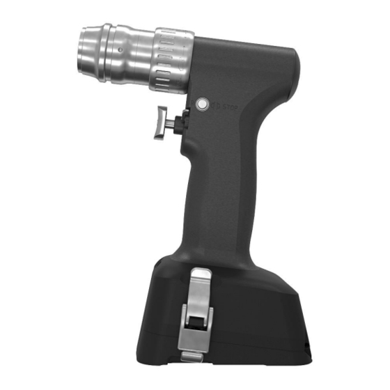
0483 2 Operation of the device Description of the controls, indication functions and symbols 2.1.1 Drilling / reaming machine (F-31-100-00) The slider in the middle position → INTERLOCK / SAFETY POSITION The device cannot be unintentionally started The slide retracted → CW rotation The slide extended →... -
Page 16: Drilling Machine (F-31-150-00)
0483 2.1.2 Drilling machine (F-31-150-00) The slider in the middle position → INTERLOCK / SAFETY POSITION The device cannot be unintentionally started The slide retracted → CW rotation The slide extended → CCW rotation The oscillating mode is on The oscillating mode is off 1 Release sleeve for attachments 2 Trigger for speed regulation 3 Slider for switching in the right direction, locking (safety position), left-hand rotation... -
Page 17: Oscillating Saws Synthes Ao Connection (F-31-300-00; F-31-301-00)
0483 2.1.3 Oscillating saws Synthes AO connection (F-31-300-00; F-31-301- The slider in the middle position → INTERLOCK / SAFETY POSITION The device cannot be unintentionally started Frequency/CPM set at step “I” Frequency/CPM set at step “II” 1 Locking ring for saw blade tension 2 Trigger for speed regulation / oscillation frequency 3 Slider for switching ON, locking (safety position), ON 4 Locking latches... -
Page 18: Oscillating Saw Stryker Sawblade Connection (F-31-310-00/F-31-311-00)
0483 2.1.4 Oscillating saw Stryker Sawblade connection (F-31-310-00/F-31- 311-00) The slider in the middle position → INTERLOCK / SAFETY POSITION The device cannot be unintentionally started Frequency/CPM set at step “I” Frequency/CPM set at step “II” 1 Locking ring for saw blade tension 2 Trigger for speed regulation / oscillation frequency 3 Slider for switching ON, locking (safety position), ON 4 Locking latches... -
Page 19: Straight Oscillating Saw Stryker Sawblade Connection (F-40-100-00/F-40-101-00)
0483 2.1.5 Straight Oscillating saw Stryker Sawblade connection (F-40-100- 00/F-40-101-00) The slider in the middle position → INTERLOCK / SAFETY POSITION The device cannot be unintentionally started Frequency/CPM set at step “I” Frequency/CPM set at step “II” 1 Locking knob for saw blade tension 2 Trigger for speed regulation / oscillation frequency 3 Slider for switching ON, locking (safety position), ON 4 Locking latches... -
Page 20: Straight Oscillating Saw Synthes Ao Connection (F-40-110-00/F-40-111-00)
0483 2.1.6 Straight Oscillating saw Synthes AO connection (F-40-110-00/F-40- 111-00) The slider in the middle position → INTERLOCK / SAFETY POSITION The device cannot be unintentionally started Frequency/CPM set at step “I” Frequency/CPM set at step “II” 1 Locking ring for saw blade tension 2 Trigger for speed regulation / oscillation frequency 3 Slider for switching ON, locking (safety position), ON 4 Locking latches... -
Page 21: Sternum Saw/ Reciprocating Saw With Keyless Chuck (F-31-601-00)
0483 2.1.7 Sternum saw/ reciprocating saw with keyless chuck (F-31-601-00) The slider in the middle position → INTERLOCK / SAFETY POSITION The device cannot be unintentionally started Frequency/CPM set at step “I” Frequency/CPM set at step “II” 1 Sawblade unlocking 2 Trigger for CPM regulation/ oscillation frequency 3 Slider for switching ON, locking (safety position), On 4 Locking latches... -
Page 22: Oscillating Reaming Machine (F-31-700-00)
0483 2.1.8 Oscillating reaming machine (F-31-700-00) The slider in the middle position → INTERLOCK / SAFETY POSITION The device cannot be unintentionally started Frequency/RPM set at step “I” Frequency/RPM set at step “II” 1 Release sleeve for attachments 2 Trigger for speed regulation 3 Slider for switching in the right direction, locking (safety position), left-hand rotation 4 Locking latches... -
Page 23: Power Pack (F-30-900-00)
0483 2.1.9 Power Pack (F-30-900-00) bottom Bottom: The lever is extended 1 Extendable lever 2 Sight glass for LED indications and lighting 2.1.10 Charging unit (e.g. F-30-900-50) 1 Charging slot 2 Power Pack display information 3 Charger display information 4 POAG connection (POAG-connection cable enclosed) on the back of the machine (not shown) 5 Mains connection (Mains connection cable enclosed) on the back of the machine (not shown) Remark: Further chargers available (dual and quadruple, see the list below). -
Page 24: Start Up
0483 Start up 2.2.1 Power pack insertion Apply the following procedures for all the handpieces. In order to ensure sterility, the power pack insertion into the sterile housing of the handpiece shall be done by two persons, out of whom, one shall be dressed in sterile clothing: The “sterile”... -
Page 25: Power Pack Removal
0483 The “unsterile” person takes the sterile funnel away from the handpiece The person in sterile clothes closes the lid. Hold the handpiece, as shown on the picture and close the latches 2.2.2 Power pack removal Apply the following procedures for all the handpieces. After surgery, remove the power pack from the handpiece and place in the charger. - Page 26 0483 Hold the handpiece as shown in the picture and open the two latches Do not turn the handpiece till the removal of the power pack. Caution: Destruction of the power pack with possible consequential damages! Grip the lid with the fingers and open Unfold the mounting bracket on the power pack and remove it from the handpiece by pulling the mounting bracket.
-
Page 27: Battery Capacity
0483 Battery capacity 2.3.1 Available battery capacity The capacity of a fully charged power pack is sufficient to carry out long and complex operations without any need of new charging. (For technical data, see 5.2 Device specification) The charging status of the power pack is indicated during surgical operations by LED lights (see 2.1.7 Power Pack) The power pack shall be kept in the charger between operations in order to ensure its full charging and readiness for use at any time. -
Page 28: Power Pack, Charging, Transport And Storage
- The power pack shall be charged exclusively in a charger of the medical bees GmbH (e.g. F-30-900- 50). Caution: Device defect! - Do not use defective power pack but send it to a competent service station of the medical bees GmbH. Warning: Danger for the patient and for the user! - Use the power pack only in the intended handpieces. -
Page 29: The Meaning Of Light Indications
0483 2.5.2 The meaning of light indications 2.5.2.1 White lights are continuously on (four lighting LEDs), the trigger activated The white light indicators signal that the motor is rotating and also serve to light the operation field. 2.5.2.2 White lights are blinking (four lighting LEDs), the trigger activated Blinking white light indicators signal that the automatic safety switch of the device has tripped because of too high temperatures. -
Page 30: Charging Units
0483 2.5.2.9 Red light indicator, the trigger activated If the light colour changes during operation (the trigger activated) into red, the machine stops and the white light indicators get simultaneously off; it is so because the load is too high and the machine is off for safety reasons. -
Page 31: Power Pack Charging
0483 2.6.3 Power pack charging The power pack to be charged shall be inserted into a free charger slot, keeping the right orientation. One power pack can be charged per one charger slot. However, all the slots in one charger can be used simultaneously (only in chargers with more than one slot). -
Page 32: Charge Control Indicators On The Charger And On The Power Pack
(applies to chargers with more than one slot) The charger slot is either not supplied with voltage or defective. In case of defect, it shall be checked and, possibly repaired by the manufacturer (the medical bees GmbH). 2.6.7 Indications on the power pack after removal from the charger If the power pack is removed from the charger before full charging, then no indicators are lit on the power pack. -
Page 33: Charger Disconnection From The Mains
0483 2.6.8 Charger disconnection from the mains Before the mains cable is unplugged from the mains, it shall be ensured there is no power pack in any of the charging slots. When the mains cable is unplugged, then also the POAG-cable can be disconnected from the building’s equipotential rail. - Page 34 - After an attachment or a cutting tool is mounted, check its proper seat by pulling. Warning: Danger for the user! - Use exclusively original attachments and tools from the medical bees GmbH or from manufacturers recommended by this Company.
-
Page 35: Attachment Mounting
0483 2.7.5 Attachment mounting Secure the device against incidental start (the slider shall be set on LOCKING / SAFETY POSITION). Warning: Danger for the user! Retract the release sleeve till the stop and hold It is recommended to hold the device in the indicated position. -
Page 36: Attachment Removal
0483 2.7.7 Attachment removal Secure the device against incidental start (the slider shall be set on LOCKING / SAFETY POSITION). Warning: Danger for the user! It is recommended to hold the device in the indicated position. The tool shall be slightly oriented upwards to avoid its drop. - Page 37 0483 2.7.8.3 Drill chuck, keyless (F-30-100-63, F-30-100-64, F-30-100-65) Rotation speed: 1000 RPM max (DRILL mode / 250 RPM max (REAM mode) Clamping width: for F-30-100-63 till Ø 6 mm (with locking) for F-30-100-64 till Ø 6 mm for F-30-100-65 till Ø 3.5 mm for F-30-100-66 till Ø...
- Page 38 0483 2.7.8.10 Harris chuck (F-30-100-54) Rotation speed: 1000 RPM max (DRILL mode / 250 RPM max (REAM mode) Cannulation: 4.3 mm 2.7.8.11 Hexagonal chuck, SW6 (F-30-100-55) Rotation speed: 1000 RPM max (DRILL mode / 250 RPM max (REAM mode) Cannulation: 4.3 mm 2.7.8.12 DIN Coupling (F-30-100-56) 2.7.8.13 Zimmer-Hall Coupling (F-30-100-57) 2.7.8.14 Assembly and disassembly of cutting tools...
- Page 39 Move the coupling sleeve backwards and insert/take out completely the tool with its slight rotation. Attention: The medical bees GmbH shall take no responsibility for the performance and results with the use of tools from another manufacturer. 2.7.8.16 Quick-action coupling for Kirschner wires (F-30-100-10 and F-30-100-15) For insertion/removal of Kirschner wires of any length and in diameter from 1.0 till 4.0 mm.
- Page 40 0483 Insert the Kirschner wire into the attachment/chuck The Kirschner wire will be slightly clamped and held in the selected position. 2.7.8.18 Kirschner wire insertion into bones Pull the lever to the handpiece in order to clamp the Kirschner wire and activate the trigger (with the slider moved for clockwise run).
- Page 41 0483 In general, the extension sleeves shall be used during all works with quick-action couplings (Kirschner wires). Warning: Danger for the user! 2.7.8.21 Adapter for radiolucent angular gear (F-30-100-25) Rotation speed: 1000 RPM max (DRILL mode) 2.7.8.22 Mounting of radiolucent angular gear on the drive unit Mount an adapter (F-30- 100-25) for the radiolucent angular gear of Synthes...
- Page 42 0483 --- Correction of drilling angle, when the cutting grooves of the drill are fully inserted into the bone. Warning: Danger for the patient and for the user! Caution: Device defect! - Drill jamming by drilling of a spike Warning: Danger for the patient! Caution: Device defect! - It shall be possible to continue operation after the following correction measures: - Drill/ Boring angle correction: Pull out the drill till the cutting grooves are visible and start the drilling...
-
Page 43: Application Of Oscillating Saws Synthes Ao Saw Blade Connection
0483 Application of oscillating saws Synthes AO saw blade connection (F-31-300-00; F-31-301-00) Attention: - If a saw is not used during a surgical procedure, put it aside and ensure that it is stored in stable condition and cannot be tilted. Caution: Device defect! - For protection against injuries, set the slider in its middle position on LOCKING / SAFETY... - Page 44 0483 The medical bees GmbH recommends saw blades of the Gomina AG Company, Risa GmbH Company or mahe medical GmbH company; the use of saw blades of other manufacturers shall not be covered by the guarantee. These saw blades are optimally customised to the requirements. Other products may reduce service and functional life of the system.
-
Page 45: Application Of Oscillating Saws
2.8.5 Recommendations for handling of saw blades medical bees GmbH requires that a new saw blade is used for every In order to obtain optimal results, the surgical procedure. In this way, it is assured that saw blades shall always be sharp and clean. Worn saw... -
Page 46: Start-Up Of Oscillating Saw
Warning: Danger for the patient and for the user! Caution: Device defect! The medical bees GmbH recommends saw blades of the Gomina AG Company, Risa GmbH Company or mahe medical GmbH company; the use of saw blades of other manufacturers shall not be covered by the guarantee. - Page 47 0483 Open the saw blade quick coupling by pressing the push button. Keep the push button pressed and remove the saw blade. To insert the new saw blade, the push button must be pressed again and the saw blade inserted. Data Revision Page...
-
Page 48: Application Of Oscillating Saws
2.9.5 Recommendations for handling of saw blades medical bees GmbH requires that a new saw blade is used for every In order to obtain optimal results, the surgical procedure. In this way, it is assured that saw blades shall always be sharp and clean. Worn saw... -
Page 49: Start Up Of Reciprocating Saw
Warning: Danger for the patient and for the user! Caution: Device defect! The medical bees GmbH recommends saw blades of the Gomina AG Company or the Risa GmbH Company; the use of saw blades of other manufacturers shall not be covered by the guarantee. These saw blades are optimally customised to the requirements. -
Page 50: Works With Saw Blades
Warning: Danger for the patient! 2.10.4 Recommendations for handling of saw blades medical bees GmbH requires that a new saw blade is used for every In order to obtain optimal results, the surgical procedure. In this way, it is assured that saw blades shall always be sharp and clean. Worn saw... -
Page 51: Application Of Sternum Saws (F-31-601-00)
Warning: Danger for the patient and for the user! Caution: Device defect! The medical bees GmbH recommends saw blades of the Gomina AG Company or the Risa GmbH Company; the use of saw blades of other manufacturers shall not be covered by the guarantee. These saw blades are optimally customised to the requirements. -
Page 52: Recommendations For Handling Of Saw Blades
2.11.4 Recommendations for handling of saw blades In order to obtain optimal results, the medical bees GmbH requires that a new saw blade is used for every surgical procedure. In this way, it is assured that saw blades shall always be sharp and clean. Worn saw... - Page 53 0483 Insert the attachment/chuck until you feel it reach the stop. Release the unlocking sleeve. In addition, check the correct seat by light pulling of the clamp. Data Revision Page IFU GA-001-02 05 February 2021 53 of 88...
-
Page 54: Application Of Oscillating Reaming Machine (F-31-700-00)
Warning: Danger for the user! - After a cutting tool is mounted, check its proper seat by pulling. Warning: Danger for the user! - Use exclusively original tools from the medical bees GmbH or from manufacturers recommended by this Company. Caution: Device defect! - Damages, resulting from the use of cutting tools of other manufacturers, shall not be covered by the warranty. -
Page 55: Cutting Tool Mounting
0483 2.12.3 Cutting tool mounting Secure the device against incidental start (the slider shall be set on LOCKING / SAFETY POSITION). Warning: Danger for the user! Retract the release sleeve till the stop and hold It is recommended to hold the device in the indicated position. -
Page 56: Cutting Tool Dismounting
0483 2.12.4 Cutting tool dismounting Secure the device against incidental start (the slider shall be set on LOCKING / SAFETY POSITION). Warning: Danger for the user! It is recommended to hold the device in the indicated position. The tool shall be slightly oriented upwards to avoid its drop. -
Page 57: Care And Maintenance (After Validated Cleaning And Sterilisation Procedures)
If there are no manufacturer’s recommendations, regarding temperature and exposure duration, then follow the instructions of the medical bees GmbH (see 3.2). Instruments shall be cleaned in a freshly set up solution. -
Page 58: Preparation To Cleaning
0483 Attention: The instruction, specified herein for the clinical processing, has been proven by the medical bees GmbH Company. It meets the requirements of ISO 17664:2004 international standard, as well as of ANSI/AAMI ST81:2004 and shall be intended for processing of non-sterile medical devices of the medical bees GmbH Company. -
Page 59: Manual Cleaning
0483 Manual cleaning 3.3.1 Machine / handpiece 1.) Remove residues Rinse handpieces (machine housings, e.g. of drilling machines, oscillating saws) under running, cold tap water for, a least, 3 minutes. Coarse impurities and deposits shall be removed with a sponge, a lint-free cloths and/or a soft brush. -
Page 60: Attachments
0483 8.) Drying Handpieces and components shall be dried with a soft lint-free cloth or in cleaned compressed air. 3.3.2 Attachments 1.) Remove residues Place the attachments (e.g. drill chucks / quick-action chucks) in cold tap water for 5 minutes. In addition, move all the moving parts at least 5 times in their entire mobility range under running water in order to loose and remove bigger deposits. -
Page 61: Mechanical Cleaning After Manual Pre-Cleaning
0483 8.) Drying Handpieces and components shall be dried with a soft lint-free cloth or in cleaned compressed air. Mechanical cleaning after manual pre-cleaning Attention: - The manual cleaning before the mechanic/automatic cleaning/disinfection is important because it ensures that cannulations and other hard accessible areas are clean. Warning: Danger for the patient! Caution: Device defect! - No cleaning / disinfection procedure, alternative to the procedures, which are described below... -
Page 62: Manual Pre-Cleaning Of The Attachments / Chucks
0483 5.) Check the components visually Repeat steps 1 through 5 till all the components are free from any visual contamination. Subsequently to the above described manual cleaning, mechanic / automatic cleaning shall follow. Further see item 3.4.3 Mechanical cleaning 3.4.2 Manual pre-cleaning of the attachments / chucks 1.) Remove residues... -
Page 63: Mechanical Cleaning
Mechanical cleaning 1.) Load a washing machine basket Place all the articles in a screen basket, specially designed by the medical bees for the system (e.g. F- 30-910-13, F-30-910-18). Ensure that all the cannulations (attachments) are placed vertically, i.e. in their upright position. - Page 64 Especially, check carefully the circumferential gasket in the lid after cleaning for any damages. The components shall properly be oiled and regularly maintained. The medical bees GmbH Company requires that maintenance is carried out at least once a year. Data Revision...
-
Page 65: Oiling / Maintenance
(F-30-900-60) or a sterilisable paraffin oil (F-30-900- 61). Wipe excessive oil with a cloth. Caution: Device defect! The medical bees GmbH Company recommends to use a lubrication stand (F-30-900-10) for oiling of devices / handpieces. Packaging Cleaned and dries products shall be placed into a screen basket in intended positions. -
Page 66: Repairs And Technical Service
(at least once a year) maintained by the manufacturer’s or authorised service station. No battery cells may be replaced. In case of any defect of the power pack, send it to the Medical bees GmbH Company or to any authorised service station. -
Page 67: Troubleshooting
The machine does not run position) position The power pack is defective Send the machine to the medical bees Service Station The overheating protection is Let the machine cool down activated, the white light is already blinking The power pack is discharged;... - Page 68 Defect of the locking Distribute some oil and move mechanism the mechanical parts. When it does not help, send the machine to the medical bees Service Station The unlocking sleeve for the Control the unlocking sleeve, attachments is jammed / possibly clean and oil.
-
Page 69: Power Pack
The trigger is blocked by Clean and oil the trigger deposits The trigger is difficult to move Defects of the mechanic part Send the machine to the medical bees Service Station Power pack Problem Possible cause Remedy/corrective action The power pack was inserted Turn the power pack by 180°... - Page 70 The power pack could Carelessness or negligence of Send the power pack to the incidentally be washed, the personnel medical bees Service Station, immersed in fluid or sterilised adhere to item 3.9 Repairs and and is thus defective. technical service.
-
Page 71: Attachments/Chucks And Tools
The Kirschner wire was Send the Kirschner wire chuck the chuck and is not moving obliquely inserted and has to the medical bees Service any farther tilted / twisted in the chuck Station Both bone and the tool heat up... -
Page 72: Charging Unit
Connect the charger by means Power pack is flashing yellow of the delivered power cable with the supply mains. Remark: If the above steps fail to remedy the problem, please contact your local Medical bees Service Station. Data Revision Page... -
Page 73: Technical Data
0483 5 Technical data Operating cycle Device Switch-on time Switch-off time Cycles F-31-100-00 drilling machine switchable 60 seconds 60 seconds F-31-150-00 drilling machine 60 seconds 60 seconds F-31-300-00; F-31-301-00 oscillating saw, 60 seconds 60 seconds Synthes AO F-31-310-00; F-31-311-00 oscillating saw 60 seconds 60 seconds Stryker... -
Page 74: Device Specification
0483 Device specification F-31-100-00 drilling / reaming machine Handpiece dimensions (without attachment) 166 x 111 x 207 mm Mass of handpiece with power pack 1850 g Continuously adjustable rotation speed 0 - 1000 rpm (drill mode) 0 - 250 rpm (ream mode) Cannulation Cannulation of Ø... - Page 75 0483 Oscillating saw Stryker (F-31-310-00; F-31-311-00) Handpiece dimensions (without attachment) 166 x 111 x 211 mm Mass of handpiece with power pack 1760 g Continuously adjustable rotation speed 0 - 9000 cpm (Step I) 0 - 10000 cpm (Step II) Protection class B, EN 60601-1 Power supply...
- Page 76 0483 F-30-601-00 sternum saw with a keyless chuck Handpiece dimensions (without attachment) 185 x 111 x 206 mm Mass of handpiece with power pack 1750 g Continuously adjustable rotation speed 0 - 7500 cpm (Step I) 0 - 10000 cpm (Step II) Protection class B, EN 60601-1 Power supply...
- Page 77 0483 F-30-900-00 Power pack (battery) Dimensions 89 x 87 x 102 mm Mass 760 g Type Li-ion Max. voltage 16.8 V Operating voltage (rated voltage) 14.4 V Capacity 2.1 Ah Typical charging time period < 90 min F-30-900-50 charger (single) Dimensions 157 x 140 x 79 mm Mass...
-
Page 78: Environmental Conditions
0483 F-30-900-52 charger (quadruple) Dimensions 636 x 140 x 79 mm Mass 6960 g Type Li-ion battery charger Input 100-240 V AC 50-60 Hz 4x 0.9 A 16.8 V DC Output 2.0 A Environmental conditions Operation Transport and storage Temperature Relative air humidity Air pressure Attention: The devices shall not be stored or operated in an explosive atmosphere. -
Page 79: Electromagnetic Compliance
0483 Electromagnetic compliance Attention: In general, mutual disturbances of electric devices cannot be fully excluded. We strongly advise compliance with the following recommendations (distances) and observance of the instructions of other used electrical equipment. In case of exposure to electromagnetic disturbances, unwanted speed fluctuations or even drop outs may occur on beesystem machines. - Page 80 0483 Table 2: Guidance and manufacturer's declaration - electromagnetic immunity The system is intended for use in the electromagnetic environment specified below. The customer of the user of the system shall ensure that the system shall be used in such environment. Interference IEC 60601-testing level Compliance level...
- Page 81 0483 Table 3: Guidance and manufacturer's declaration - electromagnetic immunity The system is intended for use in the electromagnetic environment specified below. The customer of the user of the system shall ensure that the system shall be used in such environment. Interference IEC 60601-testing Compliance level...
- Page 82 0483 Table 4: Recommended safety distances between portable and mobile RF telecommunications equipment and the system The system is intended for use in the electromagnetic environment in which RF disturbances shall be controlled. The customer or user of the system can thus help avoid electromagnetic interference by maintaining the minimum safe distance between portable and mobile RF telecommunication devices (transmitters) and the system - depending on the maximum output power of the communications equipment, as specified below.
-
Page 83: Order Information
0483 Order information The below listed products are an integral part of the User’s Manual. Every product delivery corresponds to an appropriate user’s manual. 6.1 Handpieces Item name Item number F-31-100-00 Drilling/reaming device F-31-150-00 Standard drilling machine F-31-300-00 4° oscillating saw, Synthes AO F-31-301-00 2°... -
Page 84: Attachments
0483 6.3 Attachments Item name Item name Item number Item number Wire/ pin driver (K-wire) 1-4 F-30-100-10 F-30-100-60 Jacobs drill chuck, small mm for F-31-100-00 Wire/ pin driver (K-wire) 1-4 F-30-100-15 F-30-100-61 Jacobs drill chuck, large mm for F-30-150-00 Extension for Kirschner wire F-30-100-19 F-30-100-62 Roehm drill chuck... -
Page 85: Used Symbols
0483 Item name Item name Item number Item number Spray adapter for drilling machine F-30-900-78 F-30-910-50 Cleaning brushes - set (for F-30-100-00 / F-30-150- Lid for cleaning and Cleaning and sterilisation tray F-30-910-05 sterilisation containers with a F-31-910-13 with a lid for one machine and lock accessories Cleaning and sterilisation tray... - Page 86 0483 Conformable with 93/42 EC directive 0483 Keep / store dry The device is classified as type B, regarding protection against electric shock and electric leakage currents. The device is suitable for use on patients in conformity with IEC 60601-1 standard. The device contains batteries (Li-Ion = chem.
- Page 87 0483 The power pack demonstrates functional failure, the battery is not charging: Observe the User’s Manual FAULT (The power pack is inserted into the charging unit) READY The charging unit is operational READY The charging unit is charging the power pack (yellow / orange / red light) Data Revision Page...
-
Page 88: Address / Report
0483 8 Address / Report medical bees GmbH Friedrich-Wöhler-Strasse 13 D-78576 Emmingen Phone: +49 (7465) 929 831 0 Fax: +49 (7465) 929 831 1 E-Mail: info@medical-bees.de When you do not reach us directly with a reportable event, then write an email to us, using the following email address: Meldung@medical-bees.de...
Need help?
Do you have a question about the F-31 Series and is the answer not in the manual?
Questions and answers