
Summary of Contents for Emico Noah Actuation NA Series
- Page 2 Table of Contents 1. Caution 18. Visual Indicator Setting 2. Storage 19. Wire Connection 3. Actuator Specification 20. Electric Wiring 4. Standard Specification 21. Maintenance 5. Optional Specification 22. Warranty Information 6. Performance 23. Troubleshooting 7. Exterior Parts Identification 8. Interior Parts Identification 9.
- Page 3 Final limit switch adjustment must be done after mounting the ACTUATOR to the valve. Incorrect adjustment may cause ACTUATOR failure. Over toruque swithes are factory set. Tampering with the over torque switch settings may damage the ACTUATOR and VOID the warranty. http://www.emico.co.kr...
- Page 4 SERIES MANUAL Actuator MUST be properly grounded. Use the grounding lugs provided on the inside or outside of the ACTUATOR body. To minimize the possible damage caused by condensation, be sure to energize the heater. Care should be taken when wiring 3-phase ACTUATORS. Confirm proper rotation and limit switch shutoff function during the initial operation.
- Page 5 The ACTUATOR must be stored in a clean, dry, temperature controlled area. The unit shall be stored with the cover installed and with the conduit openings sealed. Storage must be off the floor. Care must be taken to guard the ACTUATOR from condensation in extreme temperature variations. Heaters should be energized as soon as ACTUATORS are installed.
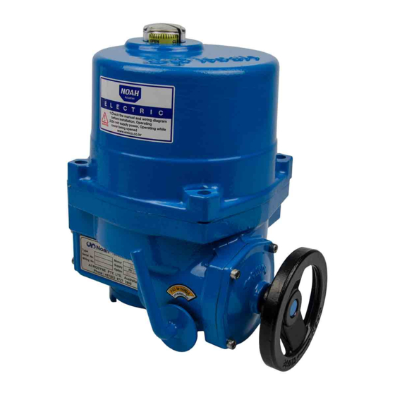
- Page 6 SERIES MANUAL The NA-Series ACTUATOR has been designed for the automation of 90 degree rotating equipment. The ACTUATOR is available in 13 different sizes with torque output from 6kg m to 250kg m. The ACTUATOR is suitable for ball valves and butterfly valves as well as dampers.
- Page 7 Hand/Auto declutch type with motor priority, the hand lever engages the manual override and will automatically reset when the motor is energized. The self locking worm gear system prevents any valve back drive from occurring The 20 watt internal heater helps to minimize condensation due to temperature and humidity changes.
- Page 8 SERIES MANUAL Watertight Ingress Protection 67 Nema 4 and 6 Enclosure Option : IP68 Option : Ex d IIB T4 -20℃to +70℃ 150℃ /1hr Ambient Temperature Option : -40℃ to +70℃ Ambient Humidity 90% RH Max (Non Condensing) DC24V 110 / 230V AC 50/60Hz Power Supply 380 / 440V AC...
- Page 9 5. Optional Specification Flameproof Enclosure Ex d IIB T4 Gb CSA, ATEX, NEPSI, GOST, KTL Watertight Enclosure IP68 IP68 1 bar 72h (KTL) Auxiliary Open, Close Limit Switches (Dry Contact) Auxiliary Open, Close Over Torque Switches (Dry Contact) Travel Angle (120˚, 135˚ , 180˚, 270˚) Potentiometer 1K Ohm Current Position Transmiter Output : DC 4-20mA...
- Page 10 SERIES MANUAL Type 200 250 kg m Output Torque 800 1000 1500 2000 2500 3000 50Hz Operating Time (90/sec) 60Hz Enclosure 67/68 67/68 67/68 67/68 67/68 67/68 67/68 67/68 67/68 67/68 67/68 67/68 67/68 67/68 Flameproof IIB T4 IIB T4 IIB T4 IIB T4 IIB T4 IIB T4 IIB T4 IIB T4 IIB T4 IIB T4 IIB T4 IIB T4 IIB T4 IIB T4 Enclosure 180 180...
- Page 11 Type Rated Current(A) 110V 50Hz Starting Current(A) Rated Current(A) 110V 60Hz Starting Current(A) Rated Current(A) 220V 50Hz Starting Current(A) Rated Current(A) 220V 60Hz Starting Current(A) Rated Current(A) 230V 50Hz Starting Current(A) Rated Current(A) 380V 50Hz Starting Current(A) Rated Current(A) 380V 60Hz Starting Current(A)
- Page 12 SERIES MANUAL NA006, NA009, NA015, NA019,NA028, NA038, NA050, NA060, NA080, NA100 Window Top Cover Bolts Top Cover ▼ Body Cable Entries Stopper Bolts Handle Cover Handle Lever Base Drive Bushing...
- Page 13 NA150, NA150, NA200, NA250, NA300 Window Top Cover Bolts Top Cover Handle Cable Entries Earth Flange Drive Bushing Bolts Gear Box Stopper Bolt Lever Base Drive Bushing 9 13...
- Page 14 SERIES MANUAL NA006, NA009, NA015, NA019, NA028, NA038, NA050 NA060, NA080, NA100, NA150, NA200, NA250, NA300 Indicator Limit Micro Switch Terminal Open Limit Cam Switch Close Limit Cam Switch Heater Torque Micro Switch Auxiliary Open, Open Torque Cam Switch Close Limit Switch Condenser Close Torque Cam Switch...
- Page 15 Before installation or use, verify the nameplate information to insure that you have the correct model number, torque, voltage and enclosure type. Type Motor Ser.No. Supply Wir.No. Option Manufacturer and Contact Info Model Number Motor Wattage A unique serial number is issued for each ACTUATOR Main Power supply voltage Electrical diagram for ACTUATOR as built.
- Page 16 SERIES MANUAL The NA-Series mounting flanges is manufactured to ISO5211 standards. If the ACTUATOR does not mount directly to the valve, then a mounting kit will need to be manufactured. Model NA006~NA009 Model NA015~NA050 Model NA150~NA300 Model NA060~NA100 (mm) Model NA006 NA015 NA028...
- Page 17 A removable blank drive bushing is supplied with each ACTUATOR that can machined to adapt to the valve stem. Remove the 4 bolts by using an L-wrench a nd the separate drive bushing from ACTUATOR. Base Drive Bushing Bolts The drive bushing should be machined to match the valve stem dimensions when the valve is in the full open or full closed position.
- Page 18 SERIES MANUAL Shaft Orientation when Butterfly Valve is in Full open Machined Drive Bushing Orientation and Type Max " Ø D" MODEL " Squre" NA006~009 Ø22 NA015~019 Ø22 NA028~050 Ø32 NA060~100 Ø42 Model NA006~NA100 (mm) Max " Ø D" MODEL "...
- Page 19 ※ EMICO mounts and cycles the valve assembly, and then calibrates the limit switch settings. 12-1-1 Confirm that the valve mounting dimensions match the ACTUATOR base and machined bushing dimensions. Base Drive Bushing Bolt 12-1-2 Pull lever to engage the handwheel, then rotate the ACTUATOR to the full clockwise/ closed position turn the valve shaft to the full close position.
- Page 20 SERIES MANUAL 12-1-3 Grease Apply a thin coat of grease to the drive bushing and install in the ACTUATOR. Apply a thin coat of grease to the valve stem and then mount the ACTUATOR to the valve as shown. Bolt Valve and Actuater add Up 12-1-4 Fasten the ACTUATOR and vavle together using stud bolts...
- Page 21 12-1-5 Engage the handwheel and rotate counter-clockwise(open). Confirm that the valve opens while turning the handwheel. 12-1-6 Remove the top cover and set the ACTUATOR limit switches. (Refer to section 15. Limit Switch Setting) 12-1-7 Adjust the length of the mechanical limit stops.
- Page 22 SERIES MANUAL ※ EMICO mounts and cycles the valve assembly, and then calibrates the limit switch settings. 12-2-1 Stem To mount the ACTUATOR and ball valve, a separate mounting kit is required. The mounting kit will need to be manufactured based on the ACTUATOR and Bracket valve mounting dimensions.
- Page 23 12-2-3 Pull the lever and turn the handwheel counter clockwise to rotate the actuator to the full open position. Also, open the valve at this time. Bolt 12-2-4 Apply a thin coat of grease to the drive bushing and install in the ACTUATOR. Apply a thin coat of grease to the valve stem .
- Page 24 SERIES MANUAL This is a general guide that is set by the company and is not an absolute standard. Application spec may vary according to the valve manufacture, environment and fluid characteristics. Consult witch our sales department about detailed and special spec. ANSI 150# Butterfly 2-way...
- Page 25 When installing an ACTUATOR, proper clearence around the ACTUATOR is required to ensure that the cover can be removed to allow for mainteriance. MODEL A (mm) NA006, 009 NA015, 019 NA028,038,050 NA060,080,100 NA150,200,250,300 EARTH 9 25...
- Page 26 SERIES MANUAL 14-1 Pull the lever located on the side of the ACTUATOR toward the handwheel. The lever should "LOCK" in position. Turn the handwheel and the ACTUATOR output will rotate. 14-2 If the lever does not "LOCK" in the upright position, then turn the handwheel halfway and pull lever to the upright position.
- Page 27 15-1-1 Confirm that the power is off. Pull lever located on the side of the ACTUATOR to engage the manual override handwheel. Rotate the handwheel counter clockwise to fully close the ACTUATOR / valve. 15-1-2 Lossen the closed limit switch cam set screw as shown. Rotate cam in the close / clockwise direction and engage the switch lever to actuate the switch If auxillary limit switches are included in the ACTUATOR,...
- Page 28 To set the open auxillary limit switch, follow the same proceedure as above except that the rotation will be counter clockwise using the open auxillary limit switch cam. The over torque switches are factory set. Tampering with the over torque switch settings may damage the ACTUATOR and VOID the warranty. For more information contact EMICO.
- Page 29 In the event of a limit switch malfunction, the mechanical limit stops will prevent the ACTUATOR from over traveling and causing damage to the valve. The mechanical limit stops should be reset whenever ant adjustment is made to the open and closed limit switches, this will protect the valve in the event of an electrical malfunction.
- Page 30 SERIES MANUAL The valve position is easily confirmed from a distance by looking at the indicator dome located on the top of the ACTUATOR cover. Non explosion proof Explosion proof 18-1 If the position shown on the indicator is incorrect, simply loosen the set screw and rotate the indicator to the correct position and retighten the set screw.
- Page 31 Failure to use the correct components may result in the failure of the ACTUATOR enclosure. EMICO is not responsible the improper installation of these ACTUATORS. 19-4 If conduit is used for cable entry, a seal fitting with setting compound must be provided close to...
- Page 32 SERIES MANUAL 20-1 Separate the cover of the ACTUATOR by lossening the four cover bolts. 20-2 Confirm that the wiring diagram located in the ACTUATOR and Wiring No. on the name plate match with each other. 20-3 Confirm that the main power and power supply described on the name plate of ACTUATOR match with each other.
- Page 33 20-9 With a 3 Phase (380, 440V) powered ACTUATOR, care must be taken to confirm the proper motor rotation when the power and signal are applied. If the ACTUATOR rotates in the reverse direction than what os expected, the limit switches will not fuction correctly and a mis-wire has occured. Corrective action needs to be taken.
- Page 34 SERIES MANUAL 21-1 Lubrication Under normal conditions, no additional grease needs to be added to the ACTUATOR. However if the ambient temperature is greater than 40℃ of the humidity is less than 15%, periodic re-greasing is recommended. The recomended grease used in the NA Series ACTUATOR is SHELL Gadus S2 V220 2.
- Page 35 ※ In addition to the above described mechanical / electric failures, other causes may be the reason for a failure based on the site conditions. For more informaion please contact EMICO for consulation. For faster service, please have all of the nameplate information availble calling the factory.
Need help?
Do you have a question about the Noah Actuation NA Series and is the answer not in the manual?
Questions and answers