Table of Contents
Advertisement
Advertisement
Table of Contents

Summary of Contents for Delta Separations CUP 15 Series
- Page 1 CUP 15 PERATING ERVICE ANUAL...
- Page 2 Copyright © 2018 by Delta Separations LLC All rights reserved. No portion of this book may be reproduced in any form without permission from Delta Separations, except as permitted by U.S. copyright law. For permission contact: sales@deltaseparations.com Printed in the United States of America...
-
Page 3: Table Of Contents
Table of Contents 1. Safety ....................Safety Notices ........................ 5 Ethyl Alcohol Safety Information ..................6 2. Basic Operation ................. System Introduction ....................... 9 Functional Overview ....................... 9 3. Technical Specifications ..............Physical Characteristics ....................12 4. Installation and Setup ..............Lifting and Transport .................... - Page 4 6. Basic Extraction Process ..............Before Extracting ......................25 Extraction Overview ..................... 25 Powering Up the System ....................26 Chilling the Alcohol (Optional) ..................26 Preparing the Material ....................27 Loading the Filter Bag ....................27 Loading the System Basket ..................27 Filling the Chamber with Alcohol ..................
-
Page 5: Safety
1. Safety Please read and follow all safety and use instructions. ONLY TRAINED PROFESSIONALS WITH A COMPLETE OPERATIONAL UNDERSTANDING OF THE EQUIPMENT—AND A FULL UNDERSTANDING OF THE RISKS ASSOCIATED WITH ALCOHOL USE—SHOULD BE AUTHORIZED TO USE THE EQUIPMENT. THE USE OF ALCOHOL HAS RISKS. -
Page 6: Ethyl Alcohol Safety Information
Ethyl Alcohol Safety Information Emergency Overview OSHA Vacated PELs: Alcohol: 1000 ppm TWA; 1900 mg/m3 TWA Personal Protective Equipment Eyes: Wear appropriate protective eyeglasses or chemical safety goggles as described by OSHA's eye and face protection regulations in 29 CFR 1910.133 or European Standard EN166. - Page 7 This equipment uses high-proof alcohol. Alcohol is a flammable liquid. DANGER Improper use may cause alcohol to discharge, resulting in an unsafe work environment. Use a properly-rated CFM fume hood, personal protective equipment (PPE), and appropriate detectors as required. Inhalation of high concentrations of Alcohol vapor may affect the central DANGER nervous system.
- Page 8 The facility must provide adequate ventilation/exhaust, as determined CAUTION by the Engineer of Record, to maintain the local atmosphere below 25% of the Lower Flammability Limit (LFL). Alcohol vapor is heavier than air and can settle in low places. CAUTION DO NOT use or store equipment or containers where they could be CAUTION exposed to high temperatures.
-
Page 9: Basic Operation
2. Basic Operation System Introduction The CUP 15-Series Alcohol Extraction System provides the ability to extract targeted botanical compounds from a diverse plant species. This unique separation technology combines closed-loop alcohol extraction with mechanical centrifugation, ensuring high- purity extractions. The system isolates specific compounds by controlling key process variables, including solvent residence times, rpm control, agitation force, and temperature. - Page 10 Figure 2-1. Process Flow Diagram...
-
Page 11: Technical Specifications
3. Technical Specifications Table 3-1 shows the specifications for the CUP 15. Never apply pressure or vacuum to the system chamber. CAUTION Never apply more than 10 psi and 15 mmHg to the system jacket. CAUTION The facility must provide adequate ventilation/exhaust, as determined CAUTION by the Engineer of Record, to maintain the local atmosphere below 25% of the Lower Flammability Limit (LFL). -
Page 12: Physical Characteristics
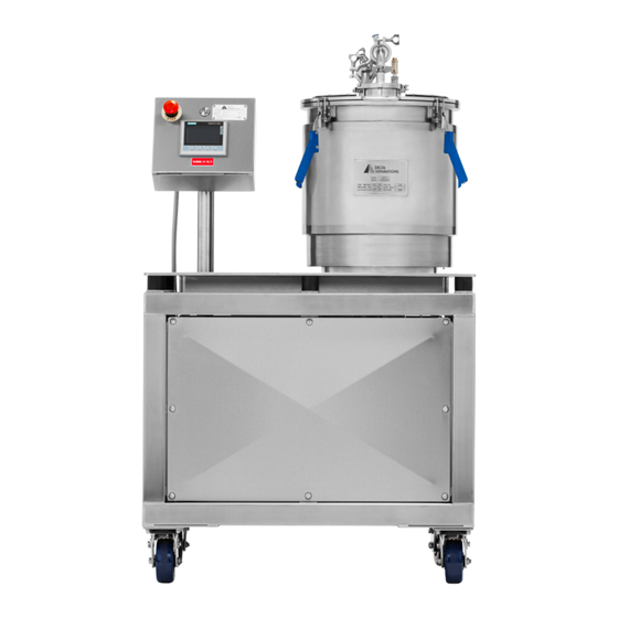
Physical Characteristics Figure 3-1 and Table 3-2 show the physical characteristics of the CUP 15. Figure 3-1. CUP 15 Physical Characteristics Width = 37 inches Width = 32 inches Depth = 25 inches Depth = 24 inches Height = 56 inches Height = 54 inches Table 3-2. -
Page 13: Installation And Setup
4. Installation and Setup Lifting and Transport All lifting and transport must be done using proper handling equipment. The system must always remain in a vertical upright position and never leaned or turned over on its side. Unpacking the Crate Remove the packing cardboard box and the second nylon packing around the centrifuge. -
Page 14: Power Requirements
Power Requirements The CUP 15 requires a dedicated 230V, 50Hz / 60 Hz, 30 amp circuit. Please ensure that all receptacles (NEMA L6-30R) match the required power ratings (see Figure 4-1). NOTE: Always plug the system into correctly grounded receptacles. Figure 4-1. -
Page 15: Environmental Safety
Environmental Safety This section includes safety recommendations that apply specifically to the CUP 15 system. Verify that the area is set up properly before installing the system. The CUP 15 has been designed to operate safely under the following environmental conditions: −... -
Page 16: Static Control
Static Control To reduce the possibility of static electricity sparks, antistatic mats can be placed around extraction and distillation equipment. Equipment will be grounded using grounding straps provided and shall conform to NEC/NFPA guidelines to help prevent static electricity and discharges. -
Page 17: Precautions And Limitation Of Use
6. Make sure all alcohol detectors are functioning properly and ready for use. 7. Make sure all pressure devices are set to correct parameters. 8. Make sure the ventilation / fume hood is turned on. Once the system has been cleaned, inspected, and the operator is familiar with the liquid transfer process, the operator may proceed to extract in the CUP. -
Page 18: Control Panel Overview
5. Control Panel Overview There are two control panels provided as part of the CUP 15. The Operator Control Panel is mounted on the same frame as the centrifuge platform and is used for direct operation of the equipment within the extraction zone. The Main Control Panel is mounted on a separate modular frame that is tethered outside the extraction zone. -
Page 19: Operator Control Panel
Operator Control Panel The Operator Control Panel consists of an HMI (Human Machine Interface), Emergency Stop Button (In the OUT position) and the HazLoc name plate. See Figure 5-2. Figure 5-2. Operator Control Panel Operator Control Panel Display The Operator Control Panel is mounted to the system motor. This is the touchscreen HMI (Human Machine Interface) for operational control. - Page 20 Figure 5-3. Operator Control Panel Display Spray Wash Cycle (Currently Not Used) The Spray Wash Cycle (Figure 5-4) is selected on the HMI where the Cycle Time and RPM Set Speed are configured to operator specifications. Push START to run the cycle. Figure 5-4.
-
Page 21: Rpm Control
Spin Dry Cycle The Spin Dry Cycle (Figure 5-6) is selected on the HMI and the sequenced spin times with corresponding rpms are set. Push START to run the cycle. Figure 5-6. Spin Dry Cycle RPM Control The RPM Control (Figure 5-7) is available for all cycles. Figure 5-7. -
Page 22: Changing Parameters
Changing Parameters To change the RPM, cycle times, or other parameters within each mode: 1. Touch the parameter box you want to change and enter a number that is between the Min and Max boundary of that parameter. See Figure 5-8. 2. - Page 23 START / STOP / PAUSE / RESET Keys Use F1-F3 on the display to Start, Stop, and Pause the cycle program. See Figure 5-10. Or press Reset (F4) to return to the cycle parameters after the system’s fault screen is flashing.
-
Page 24: Main Control Panel
Main Control Panel The Main Control Panel (Figure 5-11) includes the Power Switch to the system drive, motor and operator control panel, and an Emergency Stop button. Figure 5-11. Main Control Panel... -
Page 25: Basic Extraction Process
6. Basic Extraction Process This chapter introduces a basic extraction process. Depending on materials used and desired tincture, the details within each step of the process may be different. Before Extracting ONLY TRAINED PROFESSIONALS WITH A COMPLETE OPERATIONAL UNDERSTANDING OF THE EQUIPMENT—AND A FULL UNDERSTANDING OF THE RISKS ASSOCIATED WITH ALCOHOL USE—SHOULD BE AUTHORIZED TO USE THE EQUIPMENT. -
Page 26: Powering Up The System
Powering Up the System Prior to powering up the system: − Verify that the valves are set as follows (Figure 6-1): o Lid inlet valve: OPEN o Lid vent valve: OPEN o System discharge valve: CLOSED − Verify that the inner basket bolts are torqued to 25 foot-pounds. −... -
Page 27: Preparing The Material
Preparing the Material 1. Prepare the botanical material by milling it to a medium-coarse grind (1/4 – 3/8 inch mill size) prior to loading into the filter bag. 2. Note the input weight of the material to be loaded into the primary filter bag. Exceeding 12lbs of material is not recommended. -
Page 28: Filling The Chamber With Alcohol
2. Close the lid and securely fasten all lid clamps before proceeding. Refer to Figure 6-3. Figure 6-3. Closing the lid Filling the Chamber with Alcohol The CUP uses a pneumatic liquid transfer pump to move the alcohol from the source tank to the system chamber. -
Page 29: Recommendations For Nitrogen-Assisted Filling
Recommendations for Nitrogen-Assisted Filling The following procedure is recommended for moving fluids into the CUP15 using nitrogen assist (Compressed Air) and system kegs. 1. Close all valves on the Keg Dip Tube Manifold. Refer to Figure 6-4. Figure 6-4. Keg Dip Tube Manifold 2. - Page 30 3. Attach the ¼” Pressure Hose to the Nitrogen Tank Regulator. Use a wrench to tighten the connection. See Figure 6-6. Figure 6-6. Pressure Hose and Nitrogen Tank Regulator Connection 4. Make sure the mini ball valve is closed. Attach the other end of ¼” Pressure Hose to Keg Manifold.
- Page 31 6. Slowly turn the knob on the Regulator until 15 PSI shows on the left gauge. See Figure 6-9. Figure 6-9. Regulator Pressure of 20 PSI 7. Close the Lid INLET Valve and the System Drain Valve. See Figure 6-10. Figure 6-10.
- Page 32 8. Open ¼” Ball Valve on Keg to pressurize the keg. Do not exceed 15 PSI. See Figure 6-11. Figure 6-11. Open Ball Valve on Keg 9. Make sure lid VENT valve is open on the CUP, then open the lid INLET valve and begin filling.
-
Page 33: Running The Agitation Wash Cycle (Preferred Method)
Never fill the system while the lid VENT valve is closed. Always WARNING monitor the filling procedure and close the inlet valve when liquid is coming to an end (you will see sputtering). Always visually monitor fill levels, tanks, valves, and hoses for leakage. While the system is protected with pressure relief valves, care should be taken to ensure overfilling or pressurization of the CUP chamber does not occur. -
Page 34: Cleaning The System
During the Spin Dry Cycle, it is important to remove most of the WARNING liquid at lower RPMs (150 to 200). This keeps the system from overloading and heavily vibrating at higher RPMs. Never increase RPMs faster than the liquid can be removed from the material. Make sure the system discharge sight-glass is mostly empty before ramping up to 1800 RPM (generally 2-3 minutes). -
Page 35: System Maintenance & Support
Refer to Table 7-1 for the recommended inspection and replacement schedule for the components listed. Contact Delta Separations at 707-222-6066 or sales@deltaseparations.com for more information on maintenance specifications, replacement parts and support questions. Table 7-1. System Maintenance Schedule... -
Page 36: Flushing The Oiler
Oiler Flush Procedure This procedure should be performed every 2-4 weeks, or if the liquid in the oiler is no longer clear. The procedure flushes the internal mechanics and cleans the system of debris. The liquid in the oiler may not change color at all – It may change due to extensive heat or temperature variances. -
Page 37: Troubleshooting
8. Troubleshooting Please fill out the included form (next page) and contact us directly if you experience any problems with your CUP system. Delta Separations 707-222-6066 sales@deltaseparations.com... - Page 38 USTOMER HONE ONTACT HIPPED SERIAL #: OCATION ERSION ’ ELL ME ABOUT THE PROBLEM YOU RE EXPERIENCING ) – 1. D IRECT THE CUSTOMER TO GO TO THE SCREEN LOCATED IN FRONT OF THE SYSTEM DIRECT THEM TO “M ” ( “...
Need help?
Do you have a question about the CUP 15 Series and is the answer not in the manual?
Questions and answers
Needing the seal specs for the bearing hub on f the Centerfuge