
Summary of Contents for hyfire HFW-W2W-01
- Page 1 THE HFW-W2W-01 WIRELESS INTELLIGENT TRANSLATOR MODULE SYSTEM CONFIGURATION MANUAL WCTM Issue 3 Page 1 of 155...
- Page 2 www.acornfiresecurity.com...
-
Page 3: Table Of Contents
www.acornfiresecurity.com INDEX SECTION 1 - TRANSLATOR MODULE/EXPANDER MODULE PRE-INSTALLATION CHECKS INTRODUCTION……………………………………………………………………………………………….. PURPOSE……………………………………………………………………………………………………..… CE MARKING…………………………………………………………………………………………………..SYSTEM DESIGN AND PLANNING………………………………………………………………………..… PERSONNEL…… ………………………………………………………………………………………………. GENERAL…………………………………………………………………………………………………..….… FIELD DEVICE SUPPLY AND SUPPORT………………………………………………………………..….. INSTALLATION GUIDE…………………………………………………………………………………………. HOW TO USE THIS GUIDE…………………………………………………………………………. RELATED DOCUMENTS…………………………………………………………………………………….… WARNINGS AND CAUTIONS……………………………………………………………………………….… PRE- INSTALLATION CHECKLIST………………………………………………………………………….… SOME DO'S AND DON'TS…………………………………………………………………………………..…... - Page 4 ……………………….. Page 6 Page 7 Page 7 Page 7 Page 7 Page 7 Page 7 Page 8 Page 8 Page 8 Page 8 Page 9 Page 9 Page 10 Page 10 Page 10 Page 11 Page 12 Page 12 Page 12 Page 12 Page 13 Page 13...
- Page 5 SECTION 3 - HFW-W2W-01 INTELLIGENT TRANSLATOR MODULE INSTALLATION AND PROGRAMMING GUIDELINES INTRODUCTION………………………………………………………………………………………………. Page 27 RANGE…………………………………………………………………………………………………………. Page 28 MAXIMUM THEORETICAL Page 28 RANGE………………………………………………………………………… FEATURES……………………… Page 29 …………………………………………………………………………….. Page 29 SPECIFICATION………………………………………………………………………………………………. Page 30 WIRING CONNECTIVITY…………………………………………………………………………………….. MENU Page 31 Page 33 DESCRIPTION…………………………………………………………………………………………...
- Page 6 www.acornfiresecurity.com...
- Page 7 www.acornfiresecurity.com SECTION 5 - WIRELEX CONFIGURATION TOOL INSTALL & PROGRAMMING GUIDELINES Page 49 INTRODUCTION…………………………………………………………………………………………….. LOADING SOFTWARE…………………………………………………………………………………….. TO Page 50 START SYSTEM CONFIGURATION………………………………………………………………… ADDING Page 54 FIELD (CHILD) DEVICES TO THE TRANSLATOR MODULE……………………………… ADDING A Page 60 MULTICRITERIA DETECTOR……………………………………………………………….. ADDING AN Page 60 OPTICAL SMOKE DETECTOR…………………………………………………………….
- Page 8 www.acornfiresecurity.com...
- Page 9 www.acornfiresecurity.com SECTION 6 - ADDING AN EXPANDER MODULE INTRODUCTION………………………………………………………………………………………….…… Page 109 ADDING AN EXPANDER MODULE TO A TRANSLATOR MODULE…………………………………..Page 110 ADDING ADDITIONAL EXPANDER MODULES……………………………………………………………. Page 121 SECTION 7 - ADDITIONAL APPLICATIONS ON WIRELEX CD INTRODUCTION………………………………………………………………………………………….…… RF Page 128 ANALYSIS UTILITY………………………………………………………………….…………………..CLONEX Page 129 Page 133 FACILITY……………………………………………………………………………………..………...
- Page 10 www.acornfiresecurity.com...
-
Page 11: Introduction
DETECTION LOOP CABLING TERMINATIONS…………………………………………………………. INTRODUCTION The WIRE TO WIRELESS INTELLIGENT TRANSLATOR MODULE (HFW-W2W-01) allows for the extension of an existing, or newly installed, fire detection system with minimum interruption to the end user. All field devices and the radio programming can be completed prior to interrupting the existing system wiring minimising system down time. - Page 12 www.acornfiresecurity.com...
-
Page 13: Purpose
Low Voltage Directive 73/23/EEC (and the amending Directive 93/68/EEC) SYSTEM DESIGN AND PLANNING It is assumed that the system, of which the HFW-W2W-01 is a part, has been designed by a competent fire alarm system designer in accordance with the requirements of EN54 Part 14 and any other local codes of practice that are applicable. - Page 14 www.acornfiresecurity.com...
-
Page 15: Guide
This Installation Guide is intended to provide an installation engineer with simple guidelines on how to install a HFW-W2W-01 Translator Module, quickly and safely. For each stage in the installation and commissioning procedures a brief description is given of its purpose, complete with drawings, flow diagrams and/or other graphics to make the instructions easy to follow. - Page 16 www.acornfiresecurity.com...
-
Page 17: And Don'ts
www.acornfiresecurity.com SECTION 1 (CONT.) PRE-INSTALLATION CHECK LIST Before installing the Translator Module, you must first ensure that the following criteria have been met. Failure to do this may not only result in damage to the equipment, but may also cause problems when commissioning the equipment or adversely affect its performance. - Page 18 www.acornfiresecurity.com...
-
Page 19: Installation
SECTION 1 (CONT.) INSTALLATION The HFW-W2W-01 Translator Module is relatively simple to install providing the recommended procedures described in this Installation Guide are followed. Follow all installation instructions described in this manual. These instructions must be understood and the manufacturer's recommendations followed to avoid damage to the Fire Control Panel and associated equipment. - Page 20 www.acornfiresecurity.com...
-
Page 21: Radio Signal Performance And Stability
www.acornfiresecurity.com SECTION 1 (CONT.) RADIO SIGNAL PERFORMANCE AND STABILITY To achieve acceptable and reliable radio communication with the field radio devices, positioning of the Translator Module is important. Please observe the following procedure: Using the Radio Survey and Test Kit (HFW-STK-01) (available from Sterling Safety Systems) undertake a comprehensive radio survey to establish the location that provides the best coverage of the devices to be installed. - Page 22 www.acornfiresecurity.com...
-
Page 23: Wall Alignment
www.acornfiresecurity.com SECTION 1 (CONT.) BACK BOX FIXING WALL ALIGNMENT To prevent distortion, the Translator Module back box MUST be installed on the wall as flat as possible. Failure to comply with this requirement will result in the misalignment of the internal and external screw fixings. This will affect the IP rating of the module allowing the ingress of contamination and/or moisture. - Page 24 www.acornfiresecurity.com...
-
Page 25: Cable Instructions
www.acornfiresecurity.com SECTION 1 (CONT.) CABLE INSTRUCTIONS All wiring should comply with current IEE wiring regulations (BS7671) or the applicable local wiring regulations. Note also the requirements of EN54-14 for cabling and interconnection of a fire detection and alarm system. Use the following rules when installing cables: •... - Page 26 www.acornfiresecurity.com...
-
Page 27: Section 2 - Field Devices
…………………………………………………………………………………………………. VOICE SOUNDER/ANNUNCIATOR…………………………………………………..……………………….. INTRODUCTION The HFW-W2W-01 Translator Module supports a full range of wireless devices - Detectors, Manual Call Points, Audio and Audio-Visual devices, Input Modules and Output Modules. The table below provides detail for all the supported devices that includes: •... - Page 28 www.acornfiresecurity.com...
-
Page 29: Wireless Device Table
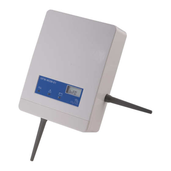
PART NUMBER GRAPHIC BASIC DESCRIPTION Intelligent hybrid wire to wireless Translator Module - complete with 2 1/4Wave HFW-W2W-01 868MHz Aerials. IP65 with appropriate glands. Intelligent hybrid wireless Expander Module. Complete with 2 x ¼Wave 868MHz HFW-EM-01 Aerials. IP65 with appropriate glands (Requires 24Vdc PSU) - Page 30 www.acornfiresecurity.com...
- Page 31 www.acornfiresecurity.com PART NUMBER GRAPHIC BASIC DESCRIPTION Intelligent hybrid wireless wall mounted Sounder (Red) 100dB(A) complete with HFW-WSR-01 batteries. For use with the hybrid wire to wireless Translator and Expander Modules. Intelligent hybrid wireless wall mounted Sounder (White) complete with batteries. For HFW-WSW-01 use with the hybrid wire to wireless Translator and Expander Modules.
- Page 32 www.acornfiresecurity.com...
- Page 33 www.acornfiresecurity.com PART NUMBER GRAPHIC BASIC DESCRIPTION Intelligent hybrid wireless (IP65) wall mounted Beacon (red) complete with batteries. For use with hybrid wire to wireless Translator and Expander Modules. HFW-BR-IP-01 Spare primary battery compatible with all hybrid wireless devices. (sold in packs of HFW-PB-01 Spare secondary battery compatible with all hybrid wireless devices.
- Page 34 www.acornfiresecurity.com...
- Page 35 www.acornfiresecurity.com PART NUMBER GRAPHIC BASIC DESCRIPTION Intelligent wireless Conventional Interface Expander Module. Allows an existing conventional system to be upgraded with a wireless zone of up to 32 input devices, HFW-CEM-01 Requires stand-alone 24V PSU and compatible software. WCTM Issue 3 Page 18 of 155...
- Page 36 www.acornfiresecurity.com...
-
Page 37: Device Dil Switch
www.acornfiresecurity.com SECTION 2 (CONT) BATTERIES The majority of wireless devices are powered from onboard power cells - the primary cell (CR123) is a 1.2Ah cell and the secondary cell (CR2032) is a 240mAh cell. (Note: The secondary cell in HFW-WS*-01, HFW-SB*-01, HFW-VS-01 and HFW-B*-01 devices, is a CR123 and not a CR2032) The field device can be transported with the secondary cell fitted - this will not drain the cell as the device only becomes active when the primary cell is fitted. - Page 38 www.acornfiresecurity.com...
- Page 39 www.acornfiresecurity.com SECTION 2 (CONT) INDIVIDUAL CHILD DEVICE GUIDANCE SENSORS Sensitivity (Optical and Multi-criteria Detectors): The default sensitivity for the smoke channel is "NORMAL". This can be altered to "LOW" or "HIGH" depending on the installation. This equates to an obscuration value of 2% (Low); 3% (Normal); 4% (High). Indications: The system allows the user to uncheck the indications for "FIRE", "BATTERY DISCHARGE"...
- Page 40 www.acornfiresecurity.com...
- Page 41 www.acornfiresecurity.com SECTION 2 (CONT) INPUT/OUTPUT MODULE INDICATIONS The Input & Output Modules have processes that can only be altered using the Wirelex software: Supervisory circuits (Input Module): Do not supervise tamper sensor: If the front cover of the module is removed and the tamper switch is activated, this indication will not be passed to the Translator Module.
- Page 42 www.acornfiresecurity.com...
-
Page 43: Wall Sounder
www.acornfiresecurity.com SECTION 2 (CONT) WALL SOUNDER The Wireless Wall Sounder has an audio output of 100dBs + 6dBs. By removing the radio PCB protective cover, using a small bladed screwdriver (preferably insulated), the sound output potentiometer can be adjusted. The Wall Sounder has three tone options: SND Switch Frequency Main... - Page 44 www.acornfiresecurity.com...
-
Page 45: Beacon
www.acornfiresecurity.com SECTION 2 (CONT) Tone selection switches are numbered 1-3 from the left. The 4 switch is the switch for setting the tone output level - switch in the OFF position gives 90dB output, switch in the ON position gives 100dB output. - Page 46 www.acornfiresecurity.com SECTION 2 (CONT) VOICE SOUNDER/ANNUNCIATOR The Voice Sounder provides the installer with a device that can be programmed with 3 messages that total ≤ 96 seconds - no single voice message can exceed 32 seconds. The message output is programmed at the Fire Control Panel at the commissioning stage.
- Page 47 www.acornfiresecurity.com...
- Page 48 HFW-W2W-01 INTELLIGENT WIRELESS TRANSLATOR MODULE INSTALLATION AND PROGRAMMING GUIDELINES WCTM Issue 3 Page 25 of 155...
- Page 49 www.acornfiresecurity.com...
-
Page 50: Section 3 - Hfw-W2W-01 Intelligent Translator Module Installation And
SECTION 3 - HFW-W2W-01 INTELLIGENT TRANSLATOR MODULE INSTALLATION AND PROGRAMMING GUIDELINES INTRODUCTION………………………………………………………………………………………………. Page 27 Page 28 RANGE…………………………………………………………………………………………………………. MAXIMUM THEORETICAL Page 28 RANGE………………………………………………………………………… FEATURES……………………… Page 29 …………………………………………………………………………….. Page 29 SPECIFICATION………………………………………………………………………………………………. Page 30 WIRING CONNECTIVITY…………………………………………………………………………………….. MENU Page 31 Page 33 DESCRIPTION…………………………………………………………………………………………... - Page 51 WCTM Issue 3 Page 26 of 155 www.acornfiresecurity.com...
-
Page 52: Introduction
INTRODUCTION The HFW-W2W-01 Intelligent Wireless Translator Module is intended to be used with a Fire Control Panel employing "Vega Protocol". This device provides a simple way of expanding a pre-existing, or new hard-wired system, using the Translator Module and its associated range of wireless devices. - Page 53 www.acornfiresecurity.com...
-
Page 54: Range
www.acornfiresecurity.com SECTION 3 (CONT) RANGE The maximum distance between the Translator Module, Expander Module and field devices is mainly affected by the fabric/structure of the building - a timber frame construction will give coverage over greater distances than if the Translator Module is used in a building constructed of a heavy ferrite core or one using reinforced concrete. - Page 55 www.acornfiresecurity.com...
-
Page 56: Specification
www.acornfiresecurity.com SECTION 3 (CONT) FEATURES • Simple and full integration into hard-wired systems. • The application of wired and wireless devices allows a fast adaptation to the changes on site. • A Maximum of 6 Translator modules can be connected to the loop. •... - Page 57 www.acornfiresecurity.com...
-
Page 58: Wiring Connectivity
www.acornfiresecurity.com SECTION 3 (CONT) WIRING CONNECTIVITY Connect the two antennae on the RF PCB located under the main processor PCB. The RF PCB is reached by releasing the Translator Module Processor PCB. The antennae should be connected as shown and the grey protective antenna sheath should then be connected into the Translator Module moulding to ensure the IP rating of the module is not affected. - Page 59 www.acornfiresecurity.com...
-
Page 60: Description
www.acornfiresecurity.com SECTION 3 (CONT) MENU DESCRIPTION • BLANK ( ): This is the normal operating level. In this condition the Translator Module is connected to the loop and working. From any sub-menu, press P1 push-button until the LCD display goes blank. When configuring the Translator Module, the Fire Control Panel will go in to fault stating a loss of the whole or part of the detection loop that the Translator Module is connected to. - Page 61 www.acornfiresecurity.com...
- Page 62 www.acornfiresecurity.com SECTION 3 (CONT) • RESET ( ): Use this sub-menu to perform a soft reset of the Translator Module. After confirming with the P2 pushbutton all the RF devices linked to the Translator Module will be reset from an existing fire and fault condition. This action is used to assist engineers on site with diagnosing soft faults or hard faults - soft faults will clear after a RESET command;...
-
Page 63: Translator Instruction Menu Breakdown
www.acornfiresecurity.com SECTION 3 (CONT) TRANSLATOR INSTRUCTION MENU BREAKDOWN If the indication appears when programming field devices, check the Start Address. This indicates that the "loop" is full. (Probable cause - setting the Start Address too high) WCTM Issue 3 Page 33 of 155... - Page 64 www.acornfiresecurity.com...
-
Page 65: Button Operation
Program the field devices on to the Translator Module. • Program the Fire Control Panel. HFW-W2W-01 TRANSLATOR PRELIMINARY PROGRAMMING • Power on the Translator Module by connecting it to the loop (connections shown on page 13). The LCD display will illuminate initially then go blank. If there is a problem with the initialisation, a indication will be displayed. -
Page 66: Device Start Address
www.acornfiresecurity.com SECTION 3 (CONT) The system code should not be the same for all Translator Modules on a fire detection loop. In the majority of systems, the channel chosen will have little effect. However, in a small number of systems, during the commissioning procedure it may become evident that one of the channels has a large amount of interference, or traffic from another system or source, and this can then be avoided by the selection of a different channel. -
Page 67: Device Programming
www.acornfiresecurity.com SECTION 3 (CONT) The Start Address will be assigned to the Translator Module. All field devices will be assigned to contiguous addresses. e.g. 1 Translator Module + 2 Manual Call Points on Fire Detection Loop 1 with Translator Module start address = 110. - Page 68 www.acornfiresecurity.com...
-
Page 69: Module Indications
www.acornfiresecurity.com SECTION 3 (CONT) TRANSLATOR MODULE INDICATIONS The following table shows the control panel behaviour according to the events generated by the Translator: DL1: blinks when the Translator Module is being polled by the Fire Control Panel. DL2: indicates a system fault condition. This is to be investigated using the Wirelex software tool DL3: illuminates constantly to indicate that an RF device has reached a low power level threshold, e.g. - Page 70 www.acornfiresecurity.com...
-
Page 71: Programming
www.acornfiresecurity.com SECTION 3 (CONT) TRANSLATOR MODULE PROGRAMMING PROGRAMMING PROCEDURE The following step-by-step procedure should be used to program the Translator Module: • Initial Translator Module configuration • Translator Module Microcell configuration • RF Device programming • Translator Module configuration load •... - Page 72 www.acornfiresecurity.com...
-
Page 73: Device Configuration
www.acornfiresecurity.com SECTION 3 (CONT) LOOP DEVICE CONFIGURATION The RF devices on the system will each take a device detection loop address on the Fire Control Panel - one for each field device and one for each Translator Module. (Expander Modules do NOT take a loop address - they are transparent to the Fire Control Panel). - Page 74 www.acornfiresecurity.com...
- Page 75 www.acornfiresecurity.com HFW-EM-01 RADIO EXPANDER MODULE INSTALLATION GUIDELINES WCTM Issue 3 Page 40 of 155...
- Page 76 www.acornfiresecurity.com...
-
Page 77: Section 4 - Hfw-Em-01 Radio Expander Module Installation Guidelines Introduction
www.acornfiresecurity.com SECTION 4 - HFW-EM-01 RADIO EXPANDER MODULE INSTALLATION GUIDELINES INTRODUCTION …………………………………………………………………………………………………. Page 41 SPECIFICATION………………………………………………………………………………………………….. Page 41 Page 42 CABLING TERMINATION - MONITORED POWER SUPPLY UNIT (PSU)….……………………………. Page 43 CABLING TERMINATION - NON-MONITORED POWER SUPPLY UNIT (PSU)…………………………. EXPANDER MODULE PCB Page 44 Page 44 CONNECTIONS……………………..……………………………………………... - Page 78 www.acornfiresecurity.com...
-
Page 79: Cabling Termination - Monitored Power Supply Unit (Psu)
www.acornfiresecurity.com SECTION 4 (CONT) CABLING TERMINATION - MONITORED POWER SUPPLY UNIT (PSU) The diagram indicates the connections required to connect a monitored PSU to an Expander Module (EM). Note:- the Jumper connection should NOT be fitted. Maximum current (I) consumption of the EM is ≤ 20mA (NOTE: A 24V PSU can be fitted to this unit) C NO Jumper to be... - Page 80 www.acornfiresecurity.com...
-
Page 81: Cabling Termination - Non-Monitored Power Supply Unit (Psu)
www.acornfiresecurity.com SECTION 4 (CONT) CABLING TERMINATION - NON-MONITORED POWER SUPPLY UNIT (PSU) The diagram below indicates the connections required to connect a non-monitored PSU to an Expander Module. NOTE:- the Jumper connection MUST be fitted. Maximum current consumption (I) of the EM is ≤ 20mA. (NOTE: A 24V PSU can be fitted to this unit) Jumper to be fitted here... - Page 82 www.acornfiresecurity.com...
- Page 83 PROGRAMMING The Expander Module can ONLY be programmed using the software supplied with the Translator Module (HFW-W2W-01). The Expander Module and associated devices should be programmed in accordance with Section 6. To use the software tool, connect a laptop computer to the RS232 connector (X3) on the Expander Module front PCB - a standard RS232 cable is to be used.
- Page 84 SECTION 4 (CONT) EXPANDER MODULE CONFIGURATION AND TOPOLOGY Expander Modules are used in association with a Translator Module (HFW-W2W-01):- one Translator Module can communicate to a maximum of seven Expander Modules: MICROCELL Translator Module 0.0.0.0.0:n LAYER Expander Module Expander Module Expander Module 1.0.0.0.0:n...
- Page 85 www.acornfiresecurity.com...
- Page 86 www.acornfiresecurity.com SECTION 4 (CONT) An alternative configuration is shown below: MICROCELL Translator Module LAYER 1 0.0.0.0.0:n LAYER 2 1.0.0.0.0:n LAYER 3 1.1.0.0.0:n LAYER 4 1.1.2.0.0:n LAYER 5 LAYER 4 1.1.2.2.0:n 1.1.1.0.0:n LAYER 6 1.1.2.2.1:n LAYER 5 1.1.2.1.0:n This configuration employs a MAXIMUM of six layers of Expander Modules (the top layer in the diagram above is a Translator Module).
- Page 87 www.acornfiresecurity.com...
- Page 88 www.acornfiresecurity.com THE WIRELEX CONFIGURATION TOOL - INSTALLATION AND PROGRAMMING GUIDELINES WCTM Issue 3 Page 47 of 155...
- Page 89 www.acornfiresecurity.com...
- Page 90 www.acornfiresecurity.com SECTION 5 - WIRELEX CONFIGURATION TOOL INSTALL & PROGRAMMING GUIDELINES Page 49 INTRODUCTION…………………………………………………………………………………………….. LOADING SOFTWARE…………………………………………………………………………………….. TO Page 50 START SYSTEM CONFIGURATION………………………………………………………………… ADDING Page 54 FIELD (CHILD) DEVICES TO THE TRANSLATOR MODULE……………………………… ADDING A Page 60 MULTICRITERIA DETECTOR……………………………………………………………….. ADDING AN Page 60 OPTICAL SMOKE DETECTOR…………………………………………………………….
- Page 91 www.acornfiresecurity.com...
-
Page 92: Introduction
www.acornfiresecurity.com SECTION 5 (cont) INTRODUCTION This section explains the facilities available when using the Wirelex Configuration Tool: • The Wirelex Configuration Tool has been designed to allow an Installation/Commissioning Engineer to program hybrid wire to wireless radio detection/initiation and alarm devices prior to programming a Fire Control Panel. •... - Page 93 www.acornfiresecurity.com...
-
Page 94: Loading Software
www.acornfiresecurity.com SECTION 5 (CONT) LOADING SOFTWARE Computer requirements: Compatible Operating Systems: Windows XP/2000/ME/98 Disk space: 50MB Minimum Processor speed: Pentium 233MHz Minimum RAM: 64MB The Wirelex software is provided on a CD. Insert the CD in to the laptop drive. The following window will appear: Press This will start the Installation Wizard for the Wirelex software. - Page 95 www.acornfiresecurity.com...
- Page 96 www.acornfiresecurity.com SECTION 5 (CONT) This will install the software in to a default folder on the computer. This can be modified if required by selecting . Once the destination folder is correct, press The following window will appear: This will add a line to the Start-up Menu so that the application can be selected from the computer main menu.
- Page 97 www.acornfiresecurity.com...
- Page 98 www.acornfiresecurity.com SECTION 5 (CONT) The following Window will appear:- This window provides a précis of the information just entered by the user. Selecting will start the installation process and display the following:- WCTM Issue 3 Page 52 of 155...
- Page 99 www.acornfiresecurity.com...
- Page 100 www.acornfiresecurity.com SECTION 5 (cont) When the software installation is complete, the following window will appear:- Click the box. Remove the CD from the CD drive and store in a safe place. The CD is not required to run this application once installed on to a computer. WCTM Issue 3 Page 53 of 155...
- Page 101 www.acornfiresecurity.com...
-
Page 102: Start System Configuration
www.acornfiresecurity.com SECTION 5 (cont) TO START SYSTEM CONFIGURATION 1.Connect the computer to the Translator Module via a standard 9 pin RS232 Serial Cable 2.Open the Wirelex software by double clicking the cursor over the Wirelex icon located on the computer desktop. The default connection within the software is to connect through COM Port 1. - Page 103 www.acornfiresecurity.com...
- Page 104 www.acornfiresecurity.com SECTION 5 (cont) c. Uncheck the "Open last system when starting the program" option. This will ensure that each time the application opens, the software will open with a "blank canvas" 3. At the Main Menu page, select "File" and "New System". The System properties sub-window will appear.
- Page 105 www.acornfiresecurity.com...
- Page 106 www.acornfiresecurity.com SECTION 5 (cont) (If building a system employing multiple Translator Modules, it is recommended each Module be assigned a different operational channel - there are seven available operational channels) WCTM Issue 3 Page 56 of 155...
- Page 107 www.acornfiresecurity.com...
- Page 108 www.acornfiresecurity.com SECTION 5 (cont) At the Main Menu page, select the "Configuration" tab. Right click the mouse over the "System icon" located in the Radiosystem topology area. Select "Add TRANSLATOR" from the drop down list. A window will appear with the Translator Module properties detailed. NB: Although the "Expander Address"...
- Page 109 www.acornfiresecurity.com...
- Page 110 www.acornfiresecurity.com SECTION 5 (cont) The only other parameter that may be changed is the "Child Expanders' Supervision Period". Once all parameters are as required, press to confirm the Translator Module values. A new Translator Module has now been added to the System configuration and the related icon appears in the Radiosystem topology tree.
- Page 111 www.acornfiresecurity.com...
- Page 112 www.acornfiresecurity.com SECTION 5 (cont) To add comments (device location, Fire Control Panel detection loop address, etc), highlight the Translator Module and right click the mouse. A small menu box will appear. Select "Comments" A "User's Comments" box will now appear (shown below). A maximum of 31 alphanumeric characters can now be entered.
- Page 113 www.acornfiresecurity.com...
-
Page 114: Field (Child) Devices To The Translator Module
www.acornfiresecurity.com SECTION 5 (cont) ADDING FIELD (CHILD) DEVICES TO THE TRANSLATOR MODULE This section details adding on to the Translator Module a child device of each type. As each device is added to the Translator Module, the device parameters that can be amended are detailed and explained. - Page 115 www.acornfiresecurity.com...
- Page 116 www.acornfiresecurity.com SECTION 5 (cont) A window will appear allowing the engineer to amend the device operating parameters. The default mode of operation for the Multi-Criteria Detector is "Fixed Rate-of-Rise". This can be changed to "Fixed" or "Rate-of Rise" by changing the "Thermo channel Type". The Multi- Criteria Detector can also be changed in to a pure Optical Detector or Thermal Detector by un-checking the associated "Process"...
- Page 117 www.acornfiresecurity.com...
-
Page 118: Optical Smoke Detector
www.acornfiresecurity.com SECTION 5 (cont) ADDING AN OPTICAL SMOKE DETECTOR To add a Smoke Detector to the Translator Module, right click the mouse over the Translator icon selecting: "Add child device" A window with the list of selectable child devices now appears. Select the device and quantity required;... - Page 119 www.acornfiresecurity.com...
- Page 120 www.acornfiresecurity.com SECTION 5 (cont) The sensitivity of the smoke channel can be amended from its default of "Normal" to "High" or "Low". Un-checking the "LED Indication" boxes - "Fire" and "Battery discharge" - will stop the device LED indicating if there is a fire activation or when the batteries reach a discharge state. The default for these indications is to remain checked and it is recommended that these two indications are left in the default state.
- Page 121 www.acornfiresecurity.com...
-
Page 122: Thermal Detector
www.acornfiresecurity.com SECTION 5 (cont) ADDING A THERMAL DETECTOR To add a Heat Detector to the Translator Module, right click the mouse over the Translator icon selecting: "Add child device" A window with the list of selectable child devices now appears. Select Thermal Detector and quantity required;... - Page 123 www.acornfiresecurity.com...
- Page 124 www.acornfiresecurity.com SECTION 5 (cont) The default mode of operation for the Thermal Detector is "Fixed Rate-of-Rise". This can be changed to "Fixed" or "Rate-of Rise" by changing the "Thermo channel Type". Un-checking the "LED Indication" boxes - "Fire" and "Battery discharge" - will stop the device LED indicating if there is a fire activation or when the batteries reach a discharge state.
- Page 125 www.acornfiresecurity.com...
-
Page 126: Manual Call Point
www.acornfiresecurity.com SECTION 5 (cont) ADDING A MANUAL CALL POINT To add a Manual Call Point to the Translator Module, right click the mouse over the Translator icon selecting: "Add child device" A window with the list of selectable child devices now appears. Select Manual Call Point and quantity required;... - Page 127 www.acornfiresecurity.com...
- Page 128 www.acornfiresecurity.com SECTION 5 (cont) Un-checking the "LED Indication" boxes - "Fire" and "Battery discharge" - will stop the device LED indicating if there is a fire activation or when the batteries reach a discharge state. The default for these indications is to remain checked and it is recommended that these two indications are left in the default state.
- Page 129 www.acornfiresecurity.com...
-
Page 130: Input Module
www.acornfiresecurity.com SECTION 5 (cont) ADDING A WIRELESS INPUT MODULE To add a Wireless Input Module to the Translator Module, right click the mouse over the Translator icon selecting: "Add child device" A window with the list of selectable child devices now appears. Select "RIG (Input Module)" and quantity required;... - Page 131 www.acornfiresecurity.com...
- Page 132 www.acornfiresecurity.com SECTION 5 (cont) The wireless Input Module has a tamper spring mounted on the device PCB. If the device cover is removed, a fault will be reported back at the Translator Module and ultimately back at the Fire Control Panel. If there is a requirement to NOT monitor a tamper fault, the check box next to "Do not supervise tamper sensor"...
- Page 133 www.acornfiresecurity.com...
-
Page 134: Powered Output Module
www.acornfiresecurity.com SECTION 5 (cont) ADDING A MAINS POWERED OUTPUT MODULE To add a Wireless Mains Powered Output Module to the Translator Module, right click the mouse over the Translator icon selecting: "Add child device" A window with the list of selectable child devices now appears. Select "OM-R (Mains Powered Output Module)"... - Page 135 www.acornfiresecurity.com...
- Page 136 www.acornfiresecurity.com SECTION 5 (cont) The wireless Mains Powered Output Module has a tamper spring mounted on the device PCB. If the device cover is removed, a fault will be reported back at the Translator Module and ultimately back at the Fire Control Panel. If there is a requirement to NOT monitor a tamper fault, the check box next to "Do not use front tamper"...
- Page 137 www.acornfiresecurity.com...
-
Page 138: Beacon
www.acornfiresecurity.com SECTION 5 (cont) ADDING A SOUNDER/SOUNDER BEACON To add a Wireless Sounder/Sounder Beacon to the Translator Module, right click the mouse over the Translator icon selecting: "Add child device" A window with the list of selectable child devices now appears. Select "Sirena-R (Sounder)" and quantity required;... - Page 139 www.acornfiresecurity.com...
- Page 140 www.acornfiresecurity.com SECTION 5 (cont) Un-checking the "LED Indication" box - "Battery discharge" - will stop the device LED indicating if the batteries reach a discharge state. The default for this indication is to remain checked and it is recommended that this indication be left in the default state. The wireless Sounder/Sounder Beacon has a tamper spring mounted on the device.
- Page 141 www.acornfiresecurity.com...
- Page 142 www.acornfiresecurity.com SECTION 5 (cont) ADDING A VOICE SOUNDER/ANNUNCIATOR To add a Wireless Voice Sounder to the Translator Module, right click the mouse over the Translator icon selecting: "Add child device" A window with the list of selectable child devices now appears. Select "Orphey-R (Voice Sounder)"...
- Page 143 www.acornfiresecurity.com...
- Page 144 www.acornfiresecurity.com SECTION 5 (cont) Un-checking the "LED Indication" box - "Battery discharge" - will stop the device LED indicating if the batteries reach a discharge state. The default for this indication is to remain checked and it is recommended that this indication be left in the default state. The "Supervisory Signal period"...
- Page 145 www.acornfiresecurity.com...
- Page 146 www.acornfiresecurity.com SECTION 5 (cont) It is possible to connect an auxiliary (external) input to the Voice Sounder using the termination block located on the Voice Sounder PCB. Termination Block for connecting an External Input on to the Voice Sounder The external input can be used to activate real-time voice messages. To enable this process, the check box marked "Reproduce signal from aux.
- Page 147 www.acornfiresecurity.com...
- Page 148 www.acornfiresecurity.com SECTION 5 (cont) ADDING A BATTERY POWERED OUTPUT MODULE To add a Battery Powered Output Module to the Translator Module, right click the mouse over the Translator icon selecting: "Add child device" A window with the list of selectable child devices now appears. Select "OM-R2 (Battery Powered Output Module)"...
- Page 149 www.acornfiresecurity.com...
- Page 150 www.acornfiresecurity.com SECTION 5 (cont) Un-checking the "LED Indication" box - "Battery discharge" - will stop the device LED indicating if the batteries reach a discharge state. The default for this indication is to remain checked and it is recommended that this indication be left in the default state.
- Page 151 www.acornfiresecurity.com...
- Page 152 www.acornfiresecurity.com SECTION 5 (cont) ADDING A BEACON To add a Wireless Beacon to the Translator Module, right click the mouse over the Translator icon selecting: "Add child device" A window with the list of selectable child devices now appears. Select "Beacon" and quantity required;...
- Page 153 www.acornfiresecurity.com...
- Page 154 www.acornfiresecurity.com SECTION 5 (cont) The wireless Beacon has a tamper spring mounted on the device that will activate if the device is removed from its base. If the tamper is activated, an indication is sent to the associated Translator Module and ultimately to the Fire Control Panel. If there is a requirement to NOT monitor this process, the check box "Do not supervise tamper detector"...
- Page 155 www.acornfiresecurity.com...
-
Page 156: Programming The Translator Module And Associated Devices
www.acornfiresecurity.com SECTION 5 (cont) PROGRAMMING THE TRANSLATOR MODULE AND ASSOCIATED DEVICES When the system architecture is complete and all child devices have been added the following will be seen at the "Configuration" tab: The Translator Module and its associated devices will need to be programmed. Right click over the Translator icon selecting the "Program TRANSLATOR"... - Page 157 www.acornfiresecurity.com...
- Page 158 www.acornfiresecurity.com SECTION 5 (cont) The following window may appear:- This is quite normal - when the software application is initially opened a new system is virtually built through the software; the software allocates a random system code to this Translator Module.
- Page 159 www.acornfiresecurity.com...
- Page 160 www.acornfiresecurity.com SECTION 5 (cont) A further sub-window will appear (see below): Select To ensure that the engineer REALLY wants to clear the Translator Module, a further confirmation sub-window will appear: Select and the following sub-window will now appear indicating that a cleaning routine is now taking place and the Translator Module is being reset to factory settings: WCTM Issue 3 Page 83 of 155...
- Page 161 www.acornfiresecurity.com...
- Page 162 www.acornfiresecurity.com SECTION 5 (cont) On completion of the cleaning process, a further sub-window will appear. This confirms to the engineer that the Translator Module is now ready for programming. Press (The cleaning process ensures that the Translator Module and associated Expander Modules will be ready to accept the new program that has just been created) WCTM Issue 3 Page 84 of 155...
- Page 163 www.acornfiresecurity.com...
- Page 164 www.acornfiresecurity.com SECTION 5 (cont) Right-click the Translator Module icon in the "Radiosystem topology" area selecting the "Program TRANSLATOR" option: A sub-window appears indicating that Translator Module programming is taking place: WCTM Issue 3 Page 85 of 155...
- Page 165 www.acornfiresecurity.com...
- Page 166 www.acornfiresecurity.com SECTION 5 (cont) On completion of programming, the user is advised that programming is complete by the appearance of a further sub-window: Press On completion of programming, the Translator Module will become BOLD in appearance. This indicates that the software application and the radio PCB are synchronised. In the "Prog." column a "+"...
- Page 167 www.acornfiresecurity.com...
-
Page 168: Programming Child Devices
www.acornfiresecurity.com SECTION 5 (cont) PROGRAMMING CHILD DEVICES Child devices can only be programmed via its associated radio interface - Translator Module or Expander Module. With the computer connected to the relevant Translator Module, right click the mouse over the first associated child device. Select: "Local Programming (RS232) >... - Page 169 www.acornfiresecurity.com...
- Page 170 www.acornfiresecurity.com SECTION 5 (cont) Ensure the Secondary Battery (CR2032) is fitted first, while the switch is in the 1 position. Move the programming switch on the back of the device to the ON position. Insert the Primary Battery (CR123A) into the device. When the primary battery is installed, the child device LED will flash four times indicating the device is in programming mode.
- Page 171 www.acornfiresecurity.com...
- Page 172 www.acornfiresecurity.com SECTION 5 (cont) This indicates that the device is now learnt on to the RF Printed Circuit Board (PCB) of the Translator Module (this is the rear PCB (secured to the Translator Module back-box by three screws) fitted within the Translator Module housing) and can now be controlled through the Configuration Tool.
- Page 173 www.acornfiresecurity.com...
-
Page 174: Process
www.acornfiresecurity.com SECTION 5 (cont) THE LOAD PROCESS The next action is extremely important! When programming the system using the Wirelex Configuration Tool, all steps/actions carried out to this point are between the Translator Module and the field devices via the rear PCB (the radio PCB). - Page 175 www.acornfiresecurity.com...
- Page 176 www.acornfiresecurity.com SECTION 5 (cont) Select the "Events" tab and check then uncheck "Turn on data exchange" select All events associated with the Translator Module and its associated devices will now be displayed. Once the Event log has stopped scrolling through, check "Turn on data exchange" again.
- Page 177 www.acornfiresecurity.com...
-
Page 178: Table
www.acornfiresecurity.com SECTION 5 (cont) THE W2W TABLE The W2W table is the process used to interface the digital aspect of the system with the analogue aspect of the system, i.e. how the analogue detection loop identifies the child devices and generates the associated analogue loop device addresses. This table can be found by highlighting the "Configuration"... - Page 179 www.acornfiresecurity.com...
- Page 180 www.acornfiresecurity.com SECTION 5 (cont) The columns shown above are: Position: This is the order the devices are learnt on to the associated Fire Control Panel in. Using the vertical scroll bar on the right hand side, it can be seen that this column shows a maximum of 32 devices - the maximum number that can be associated with a Translator Module micro-cell/cluster.
- Page 181 www.acornfiresecurity.com...
- Page 182 www.acornfiresecurity.com SECTION 5 (cont) The following window will be displayed: Highlight the "Clean table" option. This will cause a warning window to be displayed: Select . This will cause the table to blank - the devices are still present on the system; it is only the W2W table that has gone blank.
- Page 183 www.acornfiresecurity.com...
- Page 184 www.acornfiresecurity.com SECTION 5 (cont) The devices will now re-appear in a logical order starting with the devices on the Translator Module followed by devices on Expander Module 1, Expander Module 2, etc. NOTE: It is recommended that this process is only carried out during the initial commissioning of the system.
- Page 185 www.acornfiresecurity.com...
-
Page 186: Tab
www.acornfiresecurity.com SECTION 5 (cont) ADDITIONAL WIRELEX FACILITIES The application is designed for both the Security industry and the Fire Detection industry. The two additional tabs - Status and Link Quality - provide additional information for the engineer: Graphic display of RF quality of each child device. Graphic display of RF quality history. - Page 187 www.acornfiresecurity.com...
- Page 188 www.acornfiresecurity.com SECTION 5 (cont) Holding the mouse over the TXLTR in the Local Status box will bring up the Translator Module status as indicated above. Further information can be gained from this page by moving the cursor over the dark grey box In the Global partitions area, the system indicates all global partitions on the system.
- Page 189 www.acornfiresecurity.com...
- Page 190 www.acornfiresecurity.com SECTION 5 (cont) If local partition 1 is indicating any other colour than light grey ( ) (indicating no devices are attached to that partition) or dark grey ( ) (indicating that the partition is in a normal operational state), double-clicking over the coloured square will open another window.
- Page 191 www.acornfiresecurity.com...
- Page 192 www.acornfiresecurity.com SECTION 5 (cont) If there is a "FIRE" activation the associated boxes will have a square over/adjacent them. By following the same process as above, an engineer will be able to verify the child device has activated. By pressing , the engineer will return to the Status page.
- Page 193 www.acornfiresecurity.com...
-
Page 194: Tamper Fault
www.acornfiresecurity.com SECTION 5 (cont) EXAMPLES OF DISPLAYED FAULTS I. TAMPER FAULT The comment shown in the box titled "Status of devices" indicates that the child device has been removed from its base and is now in a tamper condition. Check the device to ensure it is seated correctly and when this has been confirmed, carry out a RESET command and this fault will clear. - Page 195 www.acornfiresecurity.com...
-
Page 196: Iii. Substitution Attempt
www.acornfiresecurity.com SECTION 5 (cont) III. SUBSTITUTION ATTEMPT The comment shown in the box titled "Status of devices" indicates that a device has been introduced to the system that has the same address - comparable with a hard-wired "Double Address Fault". This will happen if an apparently faulty device is removed from the system and replaced with a new... - Page 197 www.acornfiresecurity.com...
- Page 198 www.acornfiresecurity.com SECTION 5 (cont) V. GENERAL FAULT This fault occurs for a number of reasons: a. The programming switch has been moved to the "ON" position after the device has been programmed. b. The device processing has gone faulty and the expected information has not been received at the Translator Module.
- Page 199 www.acornfiresecurity.com...
- Page 200 www.acornfiresecurity.com SECTION 5 (cont) All the above faults will also be displayed in the Event Log - this is accessed by pressing the "Events" tab on the software. An example of the faults as seen in the Events Log is shown below: WCTM Issue 3 Page 103 of 155...
- Page 201 www.acornfiresecurity.com...
-
Page 202: Use Of Rf Link Quality Tab
www.acornfiresecurity.com SECTION 5 (cont) USE OF RF LINK QUALITY TAB Select the "Link Quality tab" on the Wirelex Configuration Tool. The following window will be displayed: Expanders: The Translator Module and associated Expander Modules in the cluster are displayed here. Highlighting the Expander Module you wish to investigate will display the associated child devices in the right-hand area. - Page 203 www.acornfiresecurity.com...
- Page 204 www.acornfiresecurity.com SECTION 5 (cont) LINK QUALITY TAB - CHILD DEVICE SECTION In the Child device section of the page, the following information is displayed: Device: The device type is displayed in the first column. Address: The device address is displayed in the next column. This address is allocated to the device by the associated Translator/Expander.
- Page 205 .acornfiresecurity.com...
- Page 206 www.acornfiresecurity.com SECTION 5 (cont) LINK QUALITY HISTORY GRAPH By highlighting a single device, moving the cursor over it and right clicking, two options are displayed: Show History: Selecting this option will display the RF link quality graph (shown below) Clean History: This will clean all RF link quality information - resetting the graph.
- Page 207 www.acornfiresecurity.com...
-
Page 208: Zoom In On Rf Graph
www.acornfiresecurity.com SECTION 5 (cont) ZOOM IN ON RF HISTORY GRAPH The user can zoom in on specific areas within the graph for better analysis of the RF Quality history. This is achieved by holding down the left mouse button, creating a box by moving from top left to bottom right around the interested area and then releasing the left mouse button. - Page 209 www.acornfiresecurity.com...
-
Page 210: System Configuration Code Hexadecimal-Decimal Conversion Table
www.acornfiresecurity.com SECTION 5 (cont) SYSTEM CONFIGURATION CODE HEXADECIMAL-DECIMAL CONVERSION TABLE The System Configuration Code is a code assigned to the Translator Module when it is powered on. It forms part of the encryption process employed by the Translator Module - the system code seen at the Translator Module LCD display is a decimal interpretation of a hexadecimal code, ranging from 01 to ff. -
Page 211: Introduction
www.acornfiresecurity.com SECTION 6 - ADDING A WIRELESS EXPANDER MODULE INTRODUCTION……………………………………………………………….………………………….…… Page 109 ADDING AN EXPANDER MODULE TO A TRANSLATOR MODULE……………………………………. Page 110 ADDING ADDITIONAL EXPANDER MODULES ………………………………………………………….. Page 121 INTRODUCTION To increase the area of coverage for a Translator Module a signal booster module - known as an EXPANDER MODULE (HFW-EM-01) - is available. - Page 212 www.acornfiresecurity.com...
-
Page 213: Adding An Expander Module To A Translator Module
www.acornfiresecurity.com SECTION 6 (cont) ADDING AN EXPANDER MODULE TO A TRANSLATOR MODULE Open the Wirelex software connecting the computer to the Translator Module RS232 connection using a standard 9-pin serial cable. At the Main Menu page, select "File" and "New System". The System properties sub-window will appear. - Page 214 www.acornfiresecurity.com...
- Page 215 www.acornfiresecurity.com SECTION 6 (cont) At the Main Menu page, select the "Configuration" tab. Right click the mouse over the "System icon" located in the Radiosystem topology area. Select "Add TRANSLATOR" from the drop down list. A window will appear with the Translator Module properties detailed. NB: Although the "Expander Address"...
- Page 216 www.acornfiresecurity.com...
- Page 217 www.acornfiresecurity.com SECTION 6 (cont) The only other parameter that may be changed is the "Child Expanders' Supervision Period". Once all parameters are as required, press to confirm the Translator Module values. A new Translator Module has now been added to the System configuration and the related icon appears in the Radiosystem topology tree.
- Page 218 www.acornfiresecurity.com...
- Page 219 www.acornfiresecurity.com SECTION 6 (cont) To add comments (device location, Fire Control Panel detection loop address, etc), highlight the Translator Module and right click the mouse. A small menu box will appear. Select "Comments" A "User's Comments" box will now appear (shown below). A maximum of 31 alphanumeric characters can now be entered.
- Page 220 www.acornfiresecurity.com...
- Page 221 www.acornfiresecurity.com SECTION 6 (cont) Add all child devices to the Translator Module at this point (see pages 60 - 80) for details). To add the first Expander Module, right click on the Translator Module icon in the Radiosystem topology area. A drop down window will appear. Select the "Add Expander" option: A further window will appear allowing the user to amend the operational parameters of the Expander Module.
- Page 222 www.acornfiresecurity.com...
- Page 223 www.acornfiresecurity.com SECTION 6 (cont) The user will be returned to the main screen and the following window will be displayed showing the Expander Module added to the system: To add child devices to the Expander Module, right click on the "EXP 1" icon in the "Radiosystem topology"...
- Page 224 www.acornfiresecurity.com...
- Page 225 www.acornfiresecurity.com SECTION 6 (cont) When all devices have been added, the system topology and child devices will be shown in the "Child devices" section on the "Configuration" tab: To view the devices on the Translator Module, simply left click on "TRANSLATOR" in the "Radiosystem topology"...
- Page 226 www.acornfiresecurity.com...
- Page 227 www.acornfiresecurity.com SECTION 6 (cont) If this does happen, press Right click on the Translator icon in the "Radiosystem topology" box and select "Restore TRANSLATOR to factory settings (clear)": The following window will appear: Select A further prompt will appear asking the user to confirm that a cleaning process should be undertaken.
- Page 228 www.acornfiresecurity.com...
- Page 229 www.acornfiresecurity.com SECTION 6 (cont) When the cleaning process is complete the following window will be displayed: Press . Right click on "TRANSLATOR" in the "Radiosystem topology" area se "Program TRANSLATOR" as before. The Translator Module will now be programmed. When complete, the "TRANSLATOR"...
- Page 230 www.acornfiresecurity.com...
- Page 231 www.acornfiresecurity.com SECTION 6 (cont) Right click on "EXP 1" and select "Program expander". The same warning windows may appear as for the Translator Module: Press . Carry out the cleaning process detailed on pages 117/118. On completion, select "Program expander". The Expander Module will now be programmed and on completion, "EXP 1"...
- Page 232 www.acornfiresecurity.com...
- Page 233 www.acornfiresecurity.com SECTION 6 (cont) At the Translator Module, right click on "TRANSLATOR" selecting "Program TRANSLATOR" from the drop-down list: The Translator Module will now complete the final programming sequence required for this system. On completion of the programming sequence the engineer should now carry out a LOAD command at the Translator Module, as shown on P.90.
- Page 234 www.acornfiresecurity.com...
-
Page 235: Adding Additional Expander Modules
www.acornfiresecurity.com SECTION 6 (cont) ADDING ADDITIONAL EXPANDER MODULES If adding additional Expander Modules, these can be added in three ways - daisy chain from the previous Expander Module or on the same layer as another Expander Module, or a combination of the first two. DAISY CHAIN Translator Module Expander Module... - Page 236 www.acornfiresecurity.com...
- Page 237 www.acornfiresecurity.com SECTION 6 (cont) DAISY CHAIN When adding Expander Modules in a daisy chain format, the following process should be followed. Deviation from this may result in incorrect reporting of faults and fires from trigger devices and no activation of alarm devices. Open the Wirelex software and whilst connected to the Translator Module via the RS232 port, add a Translator Module (plus child devices) and first Expander Module (plus child devices) as detailed in pages 110-116.
- Page 238 www.acornfiresecurity.com...
- Page 239 www.acornfiresecurity.com SECTION 6 (cont) The following window will be displayed showing the additional Expander Module: If devices are to be added to this Expander Module - in this instance a Thermal Heat Detector, these should be added as previously detailed. When all devices have been added, the following window should be displayed: WCTM Issue 3 Page 123 of 155...
- Page 240 www.acornfiresecurity.com...
- Page 241 www.acornfiresecurity.com SECTION 6 (cont) The following steps should be taken to ensure that all components of the system are programmed correctly: Program Translator Module Program Translator Module devices (Transfer lead to Expander Module 1) Program Expander Module "EXP 1" Program Expander Module "EXP 1" child devices (Transfer lead to Expander Module 2) Program Expander Module "EXP 2"...
- Page 242 www.acornfiresecurity.com...
- Page 243 www.acornfiresecurity.com SECTION 6 (cont) SAME LAYER If adding a second, or third, Expander Module on to the same layer - in this instance to the Translator Module, the following process should be followed. (The following procedure should be followed if adding additional Expander Modules on to the same layer). Open the Wirelex software.
- Page 244 www.acornfiresecurity.com...
- Page 245 www.acornfiresecurity.com SECTION 6 (cont) COMBINATION There may be a requirement to add Expander Modules in a combination of the previous two sequences - this could be used in an installation with multiple buildings, for example. Open the Wirelex software. With the computer connected to the Translator Module, add a Translator Module (plus child devices) and two Expander Modules (plus child devices) in a daisy chain as previously described.
- Page 246 www.acornfiresecurity.com...
- Page 247 www.acornfiresecurity.com SECTION 6 (cont) From the last image, the system can be seen as a combination of the DAISY CHAIN system and the SAME LAYER system. Programming of the system should be as follows: Program Translator Module Program Translator Module devices (Transfer lead to Expander Module) Program Expander Module "EXP 1"...
- Page 248 www.acornfiresecurity.com...
-
Page 249: Section 7 - Additional Applications On Wirelex Cd Introduction
www.acornfiresecurity.com SECTION 7 - ADDITIONAL APPLICATIONS ON WIRELEX CD INTRODUCTION………………………………………………………………………………………….…… RF Page 128 ANALYSIS UTILITY………………………………………………………………….…………………..CLONEX Page 129 Page 133 UTILITY……………………………………………………………………………………..……… VOICE Page 138 ANNUNCIATOR (ORPHEY) UTILITY……………………………………………………………… INTRODUCTION To assist an installation there are two additional software applications available on the Wirelex Configuration Tool CD: •... - Page 250 www.acornfiresecurity.com...
- Page 251 www.acornfiresecurity.com SECTION 7 (cont) RF ANALYSIS UTILITY Connect a computer to the Translator Module using a standard RS232 cable. Open the Wirelex Configuration Tool. Then: To access this facility, select the "Tools" option and at the drop down window select "RF Analyze Utility"...
- Page 252 www.acornfiresecurity.com...
- Page 253 www.acornfiresecurity.com SECTION 7 (cont) If COM Port 1 is not the correct port, select the correct port from the options displayed in the drop down window - there are only a choice of 8 ports that can be selected. In order for the computer to display the information from the Translator Module, the "Connect" box needs to be checked: NOTE: Ensure that no other application is open that uses the same port else information will not be transferred.
- Page 254 www.acornfiresecurity.com...
- Page 255 www.acornfiresecurity.com SECTION 7 (cont) When the RF channels have been selected, a real-time display will be seen: When the system changes channel, the following words are displayed on the screen and new information is displayed in the colour of the channel currently being analysed. Once all selected channels have been analysed once, the utility will refresh the scan for that channel and all successive channels.
- Page 256 www.acornfiresecurity.com...
- Page 257 www.acornfiresecurity.com SECTION 7 (cont) Interpreting the information displayed is relatively straightforward: The different coloured peaks seen above indicate packet data information being sent from devices working on that frequency. At this point, the engineer can start to de-select channels, by un-checking channels in turn at the "868MHz"...
- Page 258 www.acornfiresecurity.com...
- Page 259 www.acornfiresecurity.com SECTION 7 (cont) CLONEX UTILITY Open the Wirelex Configuration Tool. At this stage, the computer does not need to be connected to the suspect Module. A standard RS232 programming cable should be at hand. Although the Clonex utility transfers the system configuration, the Loop Address of the translator Module and associated devices is NOT transferred.
- Page 260 www.acornfiresecurity.com...
- Page 261 www.acornfiresecurity.com SECTION 7 (cont) The procedure for cloning Expander Modules is relatively straight forward. The engineer should follow the directions in the window to complete the process. When the window above is displayed, the engineer should follow the directions on the screen to complete the cloning process.
- Page 262 www.acornfiresecurity.com...
- Page 263 www.acornfiresecurity.com SECTION 7 (cont) NOTE: The Cloning process will now commence. The process reads the information stored on the Expander Module and clears the Expander Module RF PCB on completion. SECTION 6 (cont) During this phase of the process the following window will be displayed: On completion of Stage 1, the option is highlighted.
- Page 264 www.acornfiresecurity.com...
- Page 265 www.acornfiresecurity.com SECTION 7 (cont) When the PCBs have been exchanged and the antennae reconnected, select to proceed to Stage 2: The computer will now download the program previously stored in to the new Expander Module. The PC will start the cloning process by interrogating the new Translator Module. The system code on the new Translator Module will initially be different to the code from the old Translator Module.
- Page 266 www.acornfiresecurity.com...
- Page 267 www.acornfiresecurity.com SECTION 7 (cont) When the download is complete, the following window will be displayed indicating the cloning process has finished: Press and disconnect the computer from the Expander Module ensuring the front cover plate is re-instated to ensure the IP rating of the Module is maintained. The information is now stored in the radio PCB of the new Translator Module.
- Page 268 www.acornfiresecurity.com...
- Page 269 To open the utility, left click on "Tools" and select "Orphey utility" (see below) This will open the utility and allow an installer to program Hyfire Voice Annunciator devices with bespoke messages - each device will need to be programmed.
- Page 270 www.acornfiresecurity.com...
- Page 271 www.acornfiresecurity.com SECTION 7 (cont) The following page will be revealed. If the Voice Sounder is not connected to the computer, a drawing of a RS232 lead will be displayed and a warning will be shown. Select the correct COM port for communication between the computer and the device.
- Page 272 www.acornfiresecurity.com...
- Page 273 www.acornfiresecurity.com SECTION 7 (cont) Identify the sound file that will be loaded in to the Voice Sounder dragging it to the "Message 1" box in the "Computer" section. This section will be updated with the message title and the expected duration of the message. If required, the audio message can now be played back by clicking on the small sounder icon (bottom middle icon).
- Page 274 www.acornfiresecurity.com...
- Page 275 www.acornfiresecurity.com SECTION 7 (cont) This will bring up a small warning message asking the user to confirm that the message should be written in to the device. Select When the transfer commences, an additional process will appear in the "Orphey-R" section indicating time remaining for the transfer (see below).
- Page 276 www.acornfiresecurity.com...
- Page 277 www.acornfiresecurity.com SECTION 7 (cont) On completion of the download, the Device Memory" table will be updated and the sound files will be displayed. The messages can now be tested by clicking on the Speaker icon in the "Device memory" The programming process needs to be completed for each device that is to be logged on the system. WCTM Issue 3 Page 142 of 155...
- Page 278 www.acornfiresecurity.com...
-
Page 279: Connecting Laptop To An Existing Translator Module
www.acornfiresecurity.com SECTION 8 - SERVICE VISITS - DOWNLOADING TRANSLATOR MODULE PROGRAM INTRODUCTION……………………………………………………………………………………………… Page 143 CONNECTING LAPTOP TO AN EXISTING TRANSLATOR MODULE ……………………………...… Page 143 Page 152 REPLACING/CHANGING A FIELD/CHILD DEVICE……………………………………………………… INTRODUCTION During site maintenance visits, an engineer may be tasked to take readings of an existing radio microcell to ensure the radio integrity of the system is still intact - especially if there have been changes to the building layout. - Page 280 www.acornfiresecurity.com...
- Page 281 www.acornfiresecurity.com SECTION 8 (cont) A Translator Module icon will appear in the "Radiosystem topology" window and a line will be added in the "Child Devices" window. In front of this will appear a sub-window showing the Translator Module parameters. Press "OK". (There is no requirement to change the parameters). Right click on the Translator icon in the "Radiosystem topology"...
- Page 282 www.acornfiresecurity.com...
- Page 283 www.acornfiresecurity.com SECTION 8 (cont) A warning window will appear indicating that the Translator Module, the PC is connected to, belongs to another system with a different System Code. An engineer will be asked to confirm that the reading process should continue (see below). Select A small window will appear indicating that the PC is talking to the Translator Module and reading is taking place (various single line messages will appear in the window until the Translator Module reading is complete).
- Page 284 www.acornfiresecurity.com...
- Page 285 www.acornfiresecurity.com SECTION 8 (cont) On completion of the Translator Module reading, a further sub-window will appear (see below). Press The Translator Module icon in the "Radiosystem topology" window will now become bold in appearance. By left-clicking on that icon, the devices associated with that Translator Module will appear including Expander Modules.
- Page 286 www.acornfiresecurity.com...
- Page 287 www.acornfiresecurity.com SECTION 8 (cont) The Expander Module icon(s) will appear faint until they are interrogated. The Expander Module properties will need to be read to ensure that the whole Translator Module micro-cell/cluster has been downloaded correctly. There are two methods to do this: Move the RS232 lead from the Translator Module to the Expander Module.
- Page 288 www.acornfiresecurity.com...
- Page 289 www.acornfiresecurity.com SECTION 8 (cont) On completion of reading all the Expander Module properties a sub-window will appear informing the user that the properties have been successfully read: Press The Expander Module and its associated devices will now appear bold: The whole system can now be interrogated. This process should be repeated for each Expander Module within the micro-cell/cluster.
- Page 290 www.acornfiresecurity.com...
- Page 291 www.acornfiresecurity.com SECTION 8 (cont) The second method takes slightly longer to complete, but if the Expander Modules are in hard-to-access positions, the Expander Module properties can be read remotely from the Translator Module. Read the Translator Module properties as in method 1. Leave the RS232 lead connected to the Translator Module on completion.
- Page 292 www.acornfiresecurity.com...
- Page 293 www.acornfiresecurity.com SECTION 8 (cont) As long as there is a good link, the "Reading properties" percentage amount will show a constant increase. Combined with that the "Elapsed" time and "Remaining time" will sum to approximately 3 minutes. If there is a poor link, the "Reception" will start to count down from 60 seconds until a good link is re-established when the counter will be restored.
- Page 294 www.acornfiresecurity.com...
- Page 295 www.acornfiresecurity.com SECTION 8 (cont) If there are Expander Modules connected to the Translator Module, select the "Link Quality" tab, right click on "TXLTR", select the "Sending signal levels between all expanders" option followed by the "Turn on" option. This will ensure parameters of field devices associated with Expander Modules can be viewed correctly to assist in fault diagnosis.
- Page 296 www.acornfiresecurity.com...
-
Page 297: Replacing/Changing A Field/Child Device
www.acornfiresecurity.com SECTION 8 (cont) REPLACING/CHANGING A FIELD/CHILD DEVICE If a child device is suspected of being faulty or there is a requirement to change the parameters of an existing device, the Wirelex software allows this process to happen without necessarily deleting the suspect device from the system. - Page 298 www.acornfiresecurity.com...
- Page 299 www.acornfiresecurity.com SECTION 8 (cont) Insert the Primary power cell in the new device. Wait until the RF device LED indicator has blinked 4 times (to indicate the device has entered programming mode). Switch the RF device jumper from ON to the 1 position. The RF device LED will flash GREEN (showing that initial programming is completed).
- Page 300 www.acornfiresecurity.com...
- Page 301 www.acornfiresecurity.com SECTION 8 (cont) Insert the Primary power cell in the new device. Wait until the RF device LED indicator has blinked 4 times (to indicate the device has entered programming mode). Switch the RF device jumper from ON to the 1 position. The RF device LED will flash GREEN (showing that initial programming is completed).
- Page 302 www.acornfiresecurity.com...
Need help?
Do you have a question about the HFW-W2W-01 and is the answer not in the manual?
Questions and answers