Table of Contents
Advertisement
Quick Links
Advertisement
Table of Contents

Related Manuals for SMERI S-VTX

Summary of Contents for SMERI S-VTX
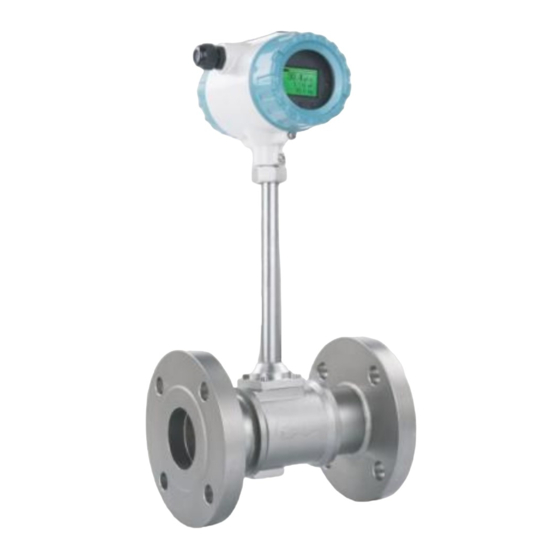
- Page 1 VORTEX FLOW METER S-VTX Instruction Manual Version 21...
-
Page 2: Table Of Contents
CONTENT 1. Introduction........................2 1.1 Principle........................ 2 1.2 Basic Parameters....................3 1.3 Flow Range......................4 1.4 Dimension......................8 1.5 Pressure Loss...................... 10 2. Installation........................11 2.1 Flange / Wafer Type Installation................ 11 2.2 Insertion Type Installation ................13 3. Wiring.......................... 15 3.1 Normal Type Without Compensation, 4-20mA+Pulse+HART......15 3.2 Normal Type Without Compensation, 4-20mA+Pulse+RS485...... - Page 3 Thank you for purchasing the digital Vortex flow meter. To ensure correct use of the instrument, please read this manual thoroughly and fully understand how to operate the instrument before operating it. ·Safety and Modification Precautions Indicates safety attentions which are dangerous. Indicates safety attentions which are needed to pay attention to.
-
Page 4: Introduction
If doubting that the instrument in the event of failure, please do not operate it If there are something wrong with the instrument or it had been damaged, please contact us. ■ Digital Vortex flow meters are thoroughly tested at the factory before shipment. -
Page 5: Basic Parameters
the average flow velocity of medium is V, d is the width of the surface of triangular prism incident flow, and D for the nominal diameter of flow meter. Then we get the computation formula: 1.2 Basic Parameters Measured Medium Liquid, Gas, Steam -40 ~... - Page 6 Relative Humidity ≦85% Pressure 86-106kPa Power Supply DC12-30V or 3.6V lithium battery powered Signal Output 4-20mA, Pulse Communication RS485 Modbus or HART 1.3 Flow Range Table 1 Liquid and Air Flow Range Table (m Liquid (m 3 /h) Air (m 3 /h) Nominal DN(mm) Extended...
- Page 7 Table 2 Saturated Steam Mass Flow Range Table (kg/h) Absolute Pressure (MPa) 120.2 133.5 143.62 151.84 158.94 164.96 170.41 Temperature (℃) Density (kg/m3) 1.129 1.651 2.163 2.669 3.17 3.667 4.162 Qmin 5.645 8.255 10.815 13.345 15.85 18.335 20.81 DN15 Qmax 56.45 82.55 108.15 133.45 158.5 183.35 208.1 Qmin 6.774 9.906 12.978 16.014 19.02 22.002 24.972...
- Page 8 Absolute Pressure (MPa) Temperature 175.36 179.68 187.96 195.04 201.37 207.11 212.37 (℃) Density 4.665 5.147 6.127 7.106 8.085 9.065 10.05 (kg/m 3 ) 23.325 25.735 30.635 35.53 40.425 45.325 50.25 Qmin DN15 233.25 257.35 306.35 355.3 404.25 453.25 502.5 Qmax 27.99 30.882 36.762...
- Page 9 Table 3 Superheated Steam Density & Relative Temperature and Pressure (Kg/m³) Temperature(℃) Absolute Pressure (MPa) 0.52 0.46 0.42 0.38 0.15 0.78 0.70 0.62 0.57 0.52 0.49 1.04 0.93 0.83 0.76 0.69 0.65 0.25 1.31 1.16 1.04 0.95 0.87 0.81 0.33 1.58 1.39 1.25 1.14...
-
Page 10: Dimension
1.4 Dimension 1.4.1 Flange Connection Type (DIN PN16 as reference) DIN PN16 Flange Connection Dimension Size n-D3 DN15 4-φ14 DN20 4-φ14 DN25 4-φ14 DN32 4-φ18 DN40 4-φ18 DN50 4-φ18 DN65 4-φ18 DN80 8-φ18 DN100 8-φ18 DN125 8-φ18 DN150 8-φ22 DN200 12-φ22 DN250 12-φ26... - Page 11 1.4.2 Wafer Connection Type Size DN15 240.5 DN20 240.5 DN25 240.5 DN32 240.5 DN40 DN50 DN65 242.5 DN80 DN100 DN125 DN150 DN200 319.5 DN250 DN300 369.5...
-
Page 12: Pressure Loss
1.4.3 Insertion Type 1.5 Pressure Loss... -
Page 13: Installation
2. Installation Caution ●Installation of the vortex flow meter must be performed by expert engineer or skilled personnel. ●Be careful that no damage is caused to people through accidentally dropping. ●When the vortex flow meter is processing with hot mediums like hot fluid or steam, be careful not to get burnt. - Page 14 Description Figure Two quarter bends on the same surface Two quarter bends on the different surface Regulating valve,half-open gate Flow regulating valve must be Valve position installed at the downstream of flow sensor. Pressure and temperature taps (for remote type vortex flow meter with T&P compensation only) Remote type vortex flow meter with pressure and temperature...
-
Page 15: Insertion Type Installation
If the length of upstream can not meet the requirement, suggest to install a flow regulator at the upstream pipeline. 2.2 Insertion Type Installation Straight Pipe Length Upstream≧15D, Downstream≧5D Recommendation 1. Open a Φ100mm round hole in the pipeline. The periphery of the hole should be free of burrs to ensure the vortex probe pass smoothly. -
Page 17: Wiring
● Attention for installation 1.The flow direction must be same as the flow indication rod, strictly forbidden to wrench the flow rod; 2. Removing burr and welding slag. 3. Wiring Warning ●The wiring of the vortex flow meter must be performed by expert engineer or skilled personnel. - Page 18 Pulse +---------------------------→7 Pulse Pulse----------------------------→6 Short circuit 7 and 8 HART 5 and 6 3.2 Normal Type Without Compensation, 4-20mA+Pulse+RS485 Connection Description DC24V + -----------------------→6 Power Supply DC24V - -----------------------→ 7 4-20mA+-----------------------→ 5 4-20mA 4-20mA - -----------------------→7 Pulse +---------------------------→8 Pulse Pulse- ----------------------------→7 RS485 +--------------------------→9 HART RS485 - -------------------------→10...
- Page 19 DC24V - -----------------------→ 6 4-20mA+-----------------------→ 5 4-20mA 4-20mA - -----------------------→6 Pulse +---------------------------→7 Pulse Pulse----------------------------→6 Short circuit 7 and 8 HART 5 and 6 3.4 With Compensation, 4-20mA+Pulse+RS485 Connection Description DC24V + -----------------------→6 Power Supply DC24V - -----------------------→ 7 4-20mA+-----------------------→ 5 4-20mA 4-20mA - -----------------------→7 Pulse +---------------------------→8...
-
Page 20: Operation
Operation Warning ● Do not open the cover with wet hands. ● When opening the cover, wait for more than 2 minutes after turning off the power. 4.1 Display Configuration ▲If the pressure sensor is set to ▲If the temperature sensor is set “automatic acquisition”... -
Page 21: Data Setting Method
4.2 Data Setting Method Data setting can be performed with the three keys on the front panel (M, S and ◆ Enter or Exit Menu Mode Enter Menu Mode In the operating mode, press the "Z" key to enter the menu mode (data entry). Exit Menu Mode In the menu mode, press the "Z"... - Page 22 Menu Description Setting method Contrast Menu Selection Normal set as 3. Press “M” button for Protection ON / OFF 2 seconds to change Min Alarm(%) Set low alarm value. Unit: % Direct Input Max Alarm(%) Set high alarm value. Unit: % Direct Input Meter Size View meter size setting.
- Page 23 Temperature Direct Input Use for gas or steam measure. Unit: ℃. (℃) PV Cutoff (%) Range: 0% ~ 20% Direct Input Damping Range: 0 ~ 64S Direct Input Set the first line display point, can be Disp. Point Menu Selection 0,1,2, 3.
-
Page 24: Advanced Function (Password Protection)
5.2 Advanced Function (Password Protection) Below menus are for expert engineers only. All settings had been done properly during flow meter calibration in factory. Do not suggest user to change any of the settings which may cause flow meter work improperly. Setting Description Menu... - Page 25 Set average calibration k-Factor (1/m 3 ) Direct M57 K-Factor Means how many pulses corresponding to Input 1m 3 flow Menu Options: m 3 , N m 3 , t, kg, Scf, cf, Pulse Factor Selectio Unit USG, UKG, bbl, lb. Set the number of output pulses corresponding to one ‘Pulse Factor Unit’.
- Page 26 There are CH_1, CH_2, CH_3 three options. CH_3 gain maximum CH_1 gain minimum Note: AMP. Menu CH2 generally used for liquid ****62 Channel measurement, which corresponds to Selection the configuration software, select X1 and X2.CH_3 generally used for gas measurement, which corresponds to the configuration software, select X1, X2 and X3.
- Page 27 Pressure acquisition mode setting. Options: manual, or auto. Manual: If select manual, the pressure value will be replaced by the M71 Pressure Menu manual setting value (the value set in basic menu “Gauge Pre. Kpa”). Measure Selection Auto: If select auto, pressure value is by automatic acquisition, need to connect with external pressure sensor.
- Page 28 Set the low pressure cutoff value. Unit: KPa. If the measured pressure value is less Direct M76 Pre. Cutoff than ‘Pre. Input Cutoff’, the pressure will be set to 0 kPa. Set the pressure bias value. Unit: Kpa. Enter the current actual pressure Direct M77 Set Pre.
- Page 29 The internal conversion frequency value corresponds to the ‘Low Flow Read Only Frequency Limit’. Modbus Direct 1 ~ 247 Addr. Input ****90 “9600”, “4800” , “2400” , “1200” , Modbus Menu “600” Baud. Selection Used to directly set the current total ****111 Direct M111 Total Preset flow value.
- Page 36 1) Adjust the pipe pressure 1) The pressure in the pipe is too and change the installation high position 2) The nominal pressure of the 2) Choose a higher nominal Leakage sensor is incorrectly selected pressure sensor 3) The seal is damaged 3) Replace the gasket 4) The sensor is corroded 4) Take anti-corrosion and...
-
Page 37: Trouble Shooting
10) Eliminate entanglement windings 11) Reduce the flow rate and 11) There is cavitation increase the pressure in the phenomenon pipe SMERI s.r.l. Via Mario Idiomi 3/13 - I 20057 Assago MI Tel. +39 02 539 8941 - E-mail: smeri@smeri.com - www.smeri.com...
Need help?
Do you have a question about the S-VTX and is the answer not in the manual?
Questions and answers