
Subscribe to Our Youtube Channel
Summary of Contents for SUS SiO
- Page 1 SiO Controller SiO2/SiO2PNP SiO3 SiO-N1 SiO3.2 SiOt SiO-N3/SiO-N3PNP Instruction Manual Version 3.9...
- Page 2 One year from purchase 1. The warranty period for this product is one year from the purchase date. SUS will repair free of charge any failure due to defects in workmanship. However, SUS will only offer carry-in service at our factories.
-
Page 3: Table Of Contents
3. 5. 1 Input/Output Connectors (SiO2/SiO2PNP) ........3-11 3. 5. 2 Input/Output Connectors (SiO3) ............3-12 3. 5. 3 Input/Output Connectors (SiO-N1) ............ 3-13 3. 5. 4 Input/Output Connectors (SiO3.2) ............ 3-14 3. 5. 5 Input/Output Connectors (SiOt) ............3-15 3. -
Page 4: Introduction
This manual is for the SiO controller (SiO2/SiO2PNP/SiO3/SiO-N1/SiO3.2/SiOt/SiO-N3/SiO-N3PNP). When using the SiO-C controller, see the “SiO-C Instruction Manual.” The contents of this manual are subject to change without prior notice for product improvement. For the latest information, visit the SUS website (http://www.sus.co.jp/). -
Page 5: Precautions For Safe Use
When disposing of the controller, treat it as general industrial waste. 1.3 Compliance with EC Directive SUS has confirmed that the products listed below meet the mandatory requirements of the EC Directive. The compliance tests have been conducted by a third party, and products that meet the compliance standards are marked with a certification mark on the case. -
Page 6: Overview
* See “7. Specifications” for details of each controller. For SiO-C controllers, see the “SiO-C Instruction Manual.” Basically, SiO controllers are used as connected with input and output Basic configuration devices as shown below. Also, the operating condition is registered by connecting a personal computer via USB. -
Page 7: Functions
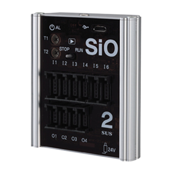
SiO Controller 3. Functions 3.1 Part Names and Functions This section describes the part names, functions, and applications of SiO controllers (SiO2/SiO2PNP/SiO3/SiO-N1/SiO3.2/SiOt/SiO-N3/SiO-N3PNP). 3.1.1 SiO2/SiO2PNP (12) (13) (3) (4) (10) (11) (14) * The same applies to SiO2PNP. Version label Part Function Connect an AC adapter here to supply 24 V DC. -
Page 8: Sio3
SiO Controller 3.1.2 SiO3 (3) (4) (10) (11) (13) (12) (12) (13) Version label Part Function Connect an AC adapter here to supply 24 V DC. Power connector * Do not supply power from other connectors. Power LED (green) Lights when the power is ON. -
Page 9: Sio-N1
SiO Controller 3.1.3 SiO-N1 (10) (11) (12) (14) Version label (15) (16) (13) Part Function Connect an AC adapter here to supply 24 V DC. Power connector * Do not supply power from other connectors. Power LED (green) Lights when the power is ON. -
Page 10: Sio3.2
SiO Controller 3.1.4 SiO3.2 (10) (11) Version label Part Function Connect an AC adapter here to supply DC 24 V. Power connector * Do not supply power from other connectors. Power LED (green) Lights when the power is ON. RUN switch Set this to RUN (right) to execute the program. -
Page 11: Siot
SiO Controller 3.1.5 SiOt Version label (13) (12) (11) (10) (14) (15) Part Function Connect an AC adapter here to supply DC 24 V. Power connector * Do not supply power from other connectors. Power LED (white) Lights when the power is ON RUN switch Set this to RUN (right) to execute the program. -
Page 12: Sio-N3/Sio-N3Pnp
SiO Controller 3.1.6 SiO – N3 / SiO – N3PNP (2) (10) (11) (15) (12) (16) (14) * The same applies to SIO – N3PNP. (13) Version label (12) Part Function Connect an AC adapter here to supply 24 V DC. -
Page 13: Principle Of Operation
3.2 Principle of Operation 3.2.1 Program The SiO controller program sets the conditions for turning ON each output and how long it is kept turned ON. Programs are edited and registered by using the dedicated software, SiO-Programmer. The following four items are set. -
Page 14: Cycle Time
The SiO controller repeats the above processes. The time required to execute these three processes once is called cycle time. The cycle time of the SiO controller is 5 msec. It is constant regardless of the number of registered programs. -
Page 15: Installation
SiO Controller 3.3 Installation 3.3.1 Installation of Controller Install the controller observing the following precautions. ◆ Avoid installation in direct sunlight. ◆ Prevent foreign matter from entering the controller. ◆ Avoid using in a place with high temperature, high humidity, dust, iron powder, cutting oil, or the like. -
Page 16: Settings
Slide the switch to “RUN” (right) to run, and to “STOP” (left) to stop the program. When the program stops, outputs are all turned OFF. Be sure to set the RUN switch to “STOP” before registering a program from the SiO-Programmer. 3.4.2 Timer Setting The SiO controller has two timer setting trimmers. -
Page 17: Input/Output
(3-pole) * O1 to O4 * When connecting input/output connectors, use e-CON-compatible connectors. SUS also provides various cables with e-CON. Visit the SUS website mentioned in “5. Options.” Input (e-CON 4-pole) pin arrangement Output (e-CON 3-pole) pin arrangement Pin No. -
Page 18: Input/Output Connectors (Sio3)
(3-pole) * OUT1 to OUT16 * When connecting input/output connectors, use e-CON-compatible connectors. SUS also provides various cables with e-CON. Visit the SUS website mentioned in “5. Options.” Input (e-CON 4-pole) pin arrangement Output (e-CON 3-pole) pin arrangement Pin No. -
Page 19: Input/Output Connectors (Sio-N1)
(3-pole) * OUT1 to OUT8 * When connecting input/output connectors, use e-CON-compatible connectors. SUS also provides various cables with e-CON. Visit the SUS website mentioned in “5. Options.” Input (e-CON 4-pole) pin arrangement Output (e-CON 3-pole) pin arrangement Pin No. -
Page 20: Input/Output Connectors (Sio3.2)
(3-pole) * OUT1 and OUT2 * When connecting input/output connectors, use e-CON-compatible connectors. SUS also provides various cables with e-CON. Visit the SUS website mentioned in “5. Options.” Input (e-CON 4-pole) pin arrangement Output (e-CON 3-pole) pin arrangement Pin No. - Page 21 * OUT1 and OUT2 * When connecting input/output connectors, use e-CON-compatible connectors. SUS also provides various cables with e-CON. Visit the SUS website mentioned in “5. Options.” Input (e-CON 4-pole) pin arrangement Output (e-CON 3-pole) pin arrangement Pin No.
-
Page 22: Input/Output Connectors (Sio-N3/Sio-N3Pnp)
* OUT1 to OUT16 * When connecting input/output connectors, use e-CON-compatible connectors. SUS also provides various cables with e-CON. Visit the SUS website mentioned in “5. Options.” Input (e-CON 4-pole) pin arrangement Output (e-CON 3-pole) pin arrangement Pin No. -
Page 23: Input Circuit Specifications
SiO Controller 3.5.5 Input Circuit Specifications (1) SiO2, SiO3, SiO-N1, SiO3.2,SiOt,SiO-N3 Inside the controller +24 V power input Item Specification 6 (SiO2) 16 (SiO3) Number of 8 (SiO-N1) Input terminal inputs 3 (SiO3.2) 4(SiOt) 16(SiO-N3) Input voltage 24 V DC ± 10%... -
Page 24: Output Circuit Specifications
Also, be sure to connect a back electromotive force absorption diode to the coil. (* 1) The total load current per controller must be 1.0 A or less. SUS also provides various cables with e-CON as options. For details, visit the SUS website mentioned in “5. Options.” SUS Corporation 3-18... -
Page 25: Examples Of Input/Output Connection (Sio2/3/N1/3.2/T/N3)
SiO Controller 3.5.7 Examples of Input/Output Connection The following are examples of connecting e-CON type SiO and input/output devices. * Connection example of NPN type 1. Connect a push-button switch to IN1. Push-button switch e-CON plug wiring Signal 2. Connect a sensor to IN2. - Page 26 Communication Full-duplex communication and half-duplex communication method 3.7.2 Setting items From SiO-Programmer to the IP address of the SiOt controller, subnet mask,Register the default gateway and port number. 3.7.3 Ethernet cable connection Connect the Ethernet cable to the Ethernet connector.
-
Page 27: Sio-Programmer
* A USB cable (Micro-B USB 2.0) is necessary for communication with the personal computer. Visit the SUS website or see the SiO-Programmer Instruction Manual for the use environment, including supported OS, and how to operate the programmer. [Main Functions] Edit programs Sets conditions for turning ON each output. - Page 28 To perform USB communication, the USB driver must be installed. For how to install the USB driver, see the following instruction manual: SiO-Programmer Instruction Manual After USB communication, disconnect the power cable of the controller body, turn off the !...
-
Page 29: Options
SiO Controller 5. Options Many options are available for the SiO controller, including various terminal blocks, input/output devices, cables, and separate connectors. * Input/output options are not available for SiO2PNP,SIO-N3PNP. Visit the SUS website for details. SUS website: http://www.sus.co.jp/ Product list -> SiO -> Compatible devices... -
Page 30: Troubleshooting
The power supply capacity may not be enough. A power supply capacity of 0.3 A is required. Action When using an AC adapter other than that supplied by SUS, check the power supply capacity. Check 5 Check the connection of the power cable and input/output cables. -
Page 31: Specifications
SiO Controller 7. Specifications SiO2 Specifications Model SiO2 Installation method GF (N) / DIN rail Power supply 24 V DC ± 10%, 0.3 A, DC plug: 5.5 mm × 2.1 mm voltage Number of 6 inputs, 4 outputs inputs/outputs Input specification 24 V DC ±... - Page 32 SiO Controller SiO2PNP Specifications Model SiO2PNP Installation method GF (N) / DIN rail Power supply 24 V DC ± 10%, 0.3 A, DC plug: 5.5 mm × 2.1 mm voltage Number of 6 inputs, 4 outputs inputs/outputs Input specification 24 V DC ± 10%, 7 mA / 24 V DC, Non-voltage contact input (PNP) Output 24 V DC ±...
- Page 33 SiO Controller SiO3 Specifications Model SiO3 Installation method GF (N) / DIN rail Power supply 24 V DC ± 10%, 0.3 A, DC plug: 5.5 mm × 2.1 mm voltage Number of 16 inputs, 16 outputs inputs/outputs Input specification 24 V DC ± 10%, 7 mA / 24 V DC, Non-voltage contact input (NPN) Output 24 V DC ±...
- Page 34 Language: SUS Original Communication USB 2.0 compliant / Micro-B type specification 485 communication: SUS Original * Only used in SiO network Temperature: 10 to 40°C, Humidity: 35 to 85%RH, No condensation Use environment Indoors without direct sunlight Use atmosphere...
- Page 35 Language: SUS Original Communication USB 2.0 compliant / Micro-B type specification 485 communication: SUS Original * Only used in SiO network Temperature: -10 to 40°C, Humidity: 35 to 85%RH, No condensation Use environment Indoors without direct sunlight Use atmosphere...
- Page 36 SiO Controller 7.11 SiOt Specifications Model SiOt Installation method GF (N) / DIN rail Power supply DC24V±10%, 0.3A, DC plug 5.5mm × 2.1mm voltage Number of 4 inputs, 2 outputs inputs/outputs Input specification 24 V DC ± 10%, 7 mA / 24 V DC, Non-voltage contact input (NPN) Output 24 V DC ±...
- Page 37 Language: SUS Original Communication USB 2.0 compliant / Micro-B type specification 485 communication: SUS Original * Only used in SiO network Temperature: -10 to 40°C, Humidity: 35 to 85%RH, No condensation Use environment Indoors without direct sunlight Use atmosphere...
- Page 38 Language: SUS Original Communication USB 2.0 compliant / Micro-B type specification 485 communication: SUS Original * Only used in SiO network Temperature: -10 to 40°C, Humidity: 35 to 85%RH, No condensation Use environment Indoors without direct sunlight Use atmosphere...
- Page 39 SiO3 added. All pages Jun. 26, 2018 SiO-N1 added. All pages SiO3.2 added. Apr. 25, 2018 All pages SiO-C deleted (See Appendix.) Jan.31.2020 Precautions for power supply added. 3-1,2,3,4,7 Sep. 16, 2020 SiOt added. All pages Sep. 30, 2020 SiO-N3/SiO-N3PNP added.
Need help?
Do you have a question about the SiO and is the answer not in the manual?
Questions and answers