Advertisement
Quick Links
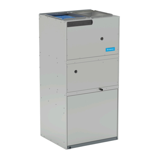
INSTALLATION AND MAINTENANCE INSTRUCTIONS
Electric Cooling / Gas Heating Packaged Unit
This is a safety alert symbol and should never be ignored. When you see this symbol on labels or in manuals, be alert to
the potential for personal injury or death.
Installation
These units are not approved for mobile home
applications. Such use could result in property damage,
personal injury, or death.
General
These instructions explain the recommended method of
installation of the MagicPak All-In-One™ HVAC system
model MGE4 gas heating with electric cooling unit and
associated electrical wiring.
These instructions, and any instructions packaged with
mating components and/or accessories, should be carefully
read prior to beginning installation. Note particularly any
CAUTIONS or WARNINGS in these instructions and all
labels on the units.
The installation of this appliance must conform to the requirements of the National Fire Protection Association; the National
Electrical Code, ANSI/NFPA No. 70 (latest edition); and any state/provincial laws or local ordinances. Local authorities
having jurisdiction should be consulted before installation is made. Such applicable regulations or requirements take
precedence over the general instructions in this manual.
Check that equipment complies with all applicable building codes, laws, and regulations for its intended use prior to installation.
508197-01
MGE4-12/14 Series
Save these instructions for future reference
WARNING
Table of Contents
Installation ...................................................................1
Start-Up .....................................................................15
Operation ...................................................................15
Maintenance ..............................................................17
Accessories ...............................................................18
Wiring Diagrams ........................................................20
Improper installation, adjustment, alteration, service
or maintenance can cause property damage, personal
injury or loss of life. Installation and service must be
performed by a licensed professional installer (or
equivalent), service agency or the gas supplier.
A Lennox International Inc. Company
*P508197-01*
CAUTION
Issue 2137
WARNING
Manufactured By
Allied Air Enterprises LLC
215 Metropolitan Drive
West Columbia, SC 29170
(P) 508197-01
Page 1 of 22
Advertisement

Subscribe to Our Youtube Channel
Related Manuals for magicpak MGE4-12 Series

Summary of Contents for magicpak MGE4-12 Series
-
Page 1: Table Of Contents
General WARNING These instructions explain the recommended method of installation of the MagicPak All-In-One™ HVAC system Improper installation, adjustment, alteration, service model MGE4 gas heating with electric cooling unit and or maintenance can cause property damage, personal associated electrical wiring. - Page 2 The MGE4 series are self-contained, gas-fired heating with electric cooling models with optional epoxy-coated WARNING coils. The unit design has been certified by Intertek Testing Services for compliance with the latest edition of The unit must be installed with approved wall sleeve the American National Standard –...
- Page 3 Unit Dimensions (in.) Model *MGE4-12-091*P 57-7/8 20-3/4 18-5/8 24-5/8 *MGE4-12-121*P *MGE4-12-181*P 59-7/8 22-3/4 20-5/8 26-5/8 *MGE4-12-241*P *MGE4-12-301*P 63-7/8 26-3/4 24-5/8 30-5/8 *MGE4-14-361*P 71-7/8 34-3/4 28-5/8 38-5/8 Top View Return Air Opening Thermostat 4” 4” Wiring Connections 16” 12” Line Voltage Knockouts (7/8”...
- Page 4 Accessibility Clearances The front of the unit must be accessible for service. A minimum clearance of 30” in front of unit is required for service. If the unit is enclosed, a door or access panel aligned with Top View the front of the unit is the preferred method of providing access.
- Page 5 Exterior Wall Wall Sleeve Top Panel Wall Sleeve Divider Panel Wall Sleeve Side Panel Wall Sleeve Side Panel Wall Sleeve Base Lag Screws with Washers Platform (field fabricated 3/4” Board Added to and supplied) Level Platform with Wall Sleeve Base Platform Height: Minimum 4”...
- Page 6 Installing and Securing Unit to Wall Sleeve Inspect the fit up of the unit to the wall sleeve. Verify that the gaskets of the wall sleeve make a complete Before installing and securing the unit to the wall sleeve, seal to the unit paying particular attention to top and make sure that the proper louver is installed.
- Page 7 CAUTION CAUTION Carbon Monoxide Poisoning Hazard For proper operation, the vent length must be correct for the installation. The unit may not operate correctly with Failure to follow the steps outlined below for each inadequate vent length. appliance connected to the venting system being placed into operation could result in carbon monoxide poisoning or death.
- Page 8 The supply and return air duct systems should be fabricated Outdoor Fan per the designed CFM and static requirements of the job (see Table 4). Ductwork should not be sized to match the dimensions of the duct connections on the unit. Vent Extension The return duct should be sealed to the unit casing and terminate outside the space containing the unit.
- Page 9 Gas Heating 0.1 “w.c. 0.2 “w.c. 0.3 “w.c. 0.4 “w.c. 0.5 “w.c. Indoor Rise Blower Range Rise Speed (F°) (F°) TAP 1 0.05 350 43 0.06 285 47 0.06 240 51 0.07 165 54 0.07 (FAN) TAP 2 0.06 370 49 0.07 315 53 0.07...
- Page 10 Gas Heating 0.1 “w.c. 0.2 “w.c. 0.3 “w.c. 0.4 “w.c. 0.5 “w.c. Indoor Rise Blower Range Rise Speed (F°) (F°) TAP 1 0.07 400 59 0.08 345 63 0.08 290 67 0.09 235 70 0.09 (FAN) TAP 2 118 0.16 625 123 0.16 565 131 0.18...
- Page 11 Gas Heating 0.1 “w.c. 0.2 “w.c. 0.3 “w.c. 0.4 “w.c. 0.5 “w.c. Indoor Rise Blower Range Rise Speed (F°) (F°) TAP 1 0.07 400 52 0.07 345 56 0.08 285 59 0.08 235 65 0.09 (FAN) TAP 2 815 206 0.28 780 210 0.28 750 215 0.29...
- Page 12 Gas Heating 0.1 “w.c. 0.2 “w.c. 0.3 “w.c. 0.4 “w.c. 0.5 “w.c. Indoor Rise Blower Range Rise Speed (F°) (F°) TAP 1 704 126 0.17 664 131 0.18 626 136 0.18 592 141 0.19 553 147 0.20 (COOL) TAP 2 1020 307 0.41 980 313 0.42 940 314...
- Page 13 Electrical Connections When proper duct design is applied, field-provided filters up to MERV 6 can typically be installed in the unit’s factory All wiring must be done in accordance with the National filter location in lieu of a washable filter. If a higher resistance Electrical Code (NEC), ANSI/NFPA No.
- Page 14 Pipe connections must be tight, and a non-hardening pipe compound resistant to liquefied petroleum gases must be WARNING used. The gas valve supplied with this furnace is rated at 1/2 Connect the gas pipe to the gas pipe connection providing psig maximum.
-
Page 15: Start-Up
Thermostat Turn on electrical power to the unit. The room thermostat should be located on an inside Set the room thermostat to the desired temperature. wall where it will not be subject to drafts, sun exposure, If the thermostat “set” temperature is above room or heat from electrical fixtures or appliances. - Page 16 Refer w.c. for propane. The furnace requires conversion for use to the wiring diagram and Blower Performance table for with propane; the MagicPak propane conversion kit must recommended heating/cooling speeds for specific models. be used.
-
Page 17: Maintenance
Rollout Switch • Cleaning the indoor and outdoor coil if covered with any foreign material, lint, leaves, or other obstructions. If for any reason the heat exchanger were to become blocked, there is a temperature sensitive switch located The condensing coil should be cleaned at a minimum once above the burners that will turn off the burners. -
Page 18: Accessories
Motors Cleaning should be as often as necessary to keep the coil clean. To clean the coil, remove the lower access panel The indoor and outdoor fan motors are permanently and blow out debris by using compressed air or water. Be lubricated and require no maintenance. - Page 19 ^ -P: Option to paint standard, aluminum, and impact-resistant louver ○ Optional: Wall sleeves and louvers can be oversized to maintain a uniform appearance NOTE: ALVRP**MGE louvers may not be oversized due to vent pipe and metal grate insert location Table 7. Accessories MagicPak Unit Accessory Nomenclature •...
-
Page 20: Wiring Diagrams
Wiring Diagrams Figure 12. Wiring Diagram - MGE 0.75 Ton through 2 Ton Page 20 of 22 Issue 2137 508197-01... - Page 21 Figure 13. Wiring Diagram - MGE 2.5 Ton 508197-01 Issue 2137 Page 21 of 22...
- Page 22 Figure 14. Wiring Diagram - MGE 3 Ton Page 22 of 22 Issue 2137 508197-01...
Need help?
Do you have a question about the MGE4-12 Series and is the answer not in the manual?
Questions and answers