
Subscribe to Our Youtube Channel
Related Manuals for Xantrex Internal M9B-HFS Series


Summary of Contents for Xantrex Internal M9B-HFS Series
- Page 1 Technical Manual for Internal M9B-HFS Serial Interface for XFR Series Power Supply TM-9BHF-XFXN...
- Page 2 The information contained in this document is confidential and is the exclusive property of Xantrex Technology Inc. It may not be disclosed to any person without the express written consent of Xantrex Technology Inc. Printed in Canada...
- Page 3 M9B-HFS INTERFACE ABOUT THIS MANUAL ABOUT THIS MANUAL This technical manual is for the M9B-HFS Interface, a microprocessor-controlled option card for all models of 1200 Watt and 2800 Watt DC output power supplies. This manual provides you with specifications, user options, and configuration instructions for the interface, along with a command set which will enable you to control your power supply from a computer console.
-
Page 4: Manual Changes
MANUAL CHANGES M9B-HFS INTERFACE MANUAL CHANGES There are no changes at this time. Release 1.0 (97/10) -
Page 5: Table Of Contents
M9B-HFS INTERFACE CONTENTS CONTENTS About This Manual ..............................i Manual Changes ................................ii Table of Contents ................................. iii List of Tables ................................v List of Illustrations ............................... v 1. FEATURES 1.1 Introduction to the Interface ........................1-1 1.2 Features and Functions .......................... - Page 6 CONTENTS M9B-HFS INTERFACE 4. CALIBRATION 4.1 Introduction ..............................4-1 4.2 Voltage Mode Calibration ..........................4-1 4.2.1 Voltage Calibration Setup Procedure ....................4-1 4.2.2 Voltage Program Calibration Procedure ..................4-2 4.2.3 Voltage Readback Calibration Procedure ..................4-2 4.3 Current Mode Calibration ..........................4-3 4.3.1 Current Calibration Setup ........................
- Page 7 M9B-HFS INTERFACE CONTENTS List of Tables Table 2.2-1 M9B-HFS Setup Procedure ........................2-2 Table 2.3-1 S1 Switch Settings for Baud Rate Selection ..................2-4 Table 2.3-2 S1 FLOW Switch Setting for Flow Control ..................2-4 Table 2.4-1 Receiver/Transmitter Pair ........................2-5 Table 2.5-1 Remote Mode Power On Default Settings ...................
-
Page 9: Features
M9B-HFS INTERFACE FEATURES FEATURES Introduction to the Interface The M9B-HFS Interface is a microprocessor-controlled option card for the 1200 Watt or 2800 Watt model power supply. Installed internally, the M9B-HFS gives you remote digital control of simple test systems. It has 16-bit resolution for programming and readback and uses bit serial protocol for sending data between the computer and the interface. -
Page 10: Features And Functions
FEATURES M9B-HFS INTERFACE Features and Functions 1.2.1 Features • Fiber optic receiver/transmitter pair • 16-bit programming and readback of voltage and current • Programmable soft limits for voltage and current • Programmable over voltage protection with reset • Easy-to-use, self-documenting command set •... -
Page 11: Inspection And Configuration
M9B-HFS INTERFACE INSPECTION AND CONFIGURATION INSPECTION AND CONFIGURATION Initial Inspection CAUTION If you remove the unit's cover, use proper static control techniques to avoid damage to static-sensitive components on the printed circuit board. The M9B-HFS interface card typically comes pre-installed if you have ordered the interface with a power supply. If you have ordered the interface separately, your sales/service representative can ensure it is correctly installed in your previously -purchased power supply. -
Page 12: M9B-Hfs Setup Procedure
INSPECTION AND CONFIGURATION M9B-HFS INTERFACE M9B-HFS Setup Procedure To use this product, you must have the following equipment: • Two fiber optic cables, or one duplex fiber optic cable (for receiving and transmitting) • Computer with a fiber optic serial interface •... -
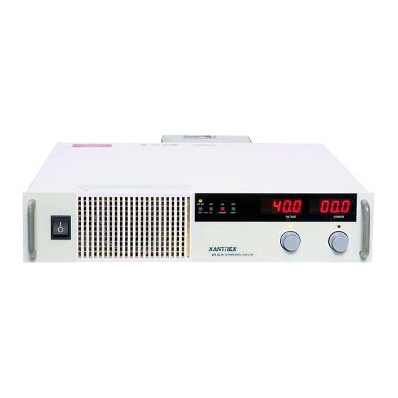
Page 13: Figure 2.2-1 Front Panel
M9B-HFS INTERFACE INSPECTION AND CONFIGURATION Remote Programming LED (REM) Return to Local Button (LOCAL) Addressed LED (ADR) Fault LED (FLT) Error LED (ERR) Polarity LED (POL) Figure 2.2-1 Front Panel (2800 Watt DC Power Supply shown) S1 Communication Switch 1 Baud rate selection (B3) 2 Baud rate selection (B2) 3 Baud rate selection (B1) Receiver LED... -
Page 14: S1 Switch Communication Settings
INSPECTION AND CONFIGURATION M9B-HFS INTERFACE S1 Switch Communication Settings 2.3.1 Baud Rate Selection Serial transmission sends and receives data in bit streams at fixed bit rates. Both the computer and the interface must have the same bit rate setting for proper communication. Use switches B3, B2, and B1 on the rear panel S1 switch to select the power supply's rate of transmission in bits per second. -
Page 15: Connecting The Fiber Optic Line
M9B-HFS INTERFACE INSPECTION AND CONFIGURATION Connecting the Fiber Optic Line To connect the option card to a computer, you need: • two fiber optic cables, or one duplex fiber optic cable (for receiving and transmitting) • a computer with a fiber optic serial port 2.4.1 Fiber Optic Cable The maximum fiber optic cable length for connecting the M9B-HFS option card to a computer is 20 meters. -
Page 16: Power On Conditions
INSPECTION AND CONFIGURATION M9B-HFS INTERFACE Power ON Conditions 2.5.1 Default Conditions The M9B-HFS Interface is configured to operate in remote mode when powered on. The default command setting Remote Enable (REN) ON enables remote digital control of the supply. With REN ON, the supply will respond to any command you send from the computer. -
Page 17: Computer Settings
M9B-HFS INTERFACE INSPECTION AND CONFIGURATION Computer Settings For serial communication, the computer and the power supply must share the same communication settings. Make sure that the settings of the computer and of the power supply agree with those shown in Table 2.6-1. -
Page 18: Figure 2.7-1 M9B-Hfs Interface Pcb
INSPECTION AND CONFIGURATION M9B-HFS INTERFACE CAUTION Use proper static control techniques to avoid damage to static-sensitive components on the printed circuit board. JUMPER SELECTION OVP Control Selection [closed] (default) See Table 2.7-1 [open] Front panel OVP control User TTL Shutdown (S/D) Selection [1-2] User TTL S/D line active low [2-3] User TTL S/D line active high [default] J104... -
Page 19: Ttl Shutdown
M9B-HFS INTERFACE INSPECTION AND CONFIGURATION 2.7.2 TTL Shutdown You can use the Shutdown function to disable or enable the supply's output. Disabling the supply using TTL shutdown allows you to make adjustments to the load or the power supply without shutting down the power supply. -
Page 20: J7 User Signal Connector
INSPECTION AND CONFIGURATION M9B-HFS INTERFACE J7 User Signal Connector Auxiliary connector J7, located on the HFS-M9B Interface rear panel, provides several signals to increase your operating control of the supply. These signals are dependent on the operator's design and uses. The operation of the J7 signal requires that you provide external Vcc and ground connection. -
Page 21: M9B-Hfs Operation
M9B-HFS INTERFACE M9B-HFS OPERATION M9B-HFS OPERATION The M9B-HFS interface controller card enables you to send and receive data via the fiber optic communication line which connects your supply to a computer. You can use the computer controller to issue commands to the power supply for programming, queries, calibration, or status. -
Page 22: Table 3.1-1 Command Parameters
M9B-HFS OPERATION M9B-HFS INTERFACE 3.1.2 Command Format and Parameters (continued) Table 3.1-1 Command Parameters Parameter Description Form <current>, <Ihi>, <Ilo> The current in amps or milliamps. If no unit is given, the <float> default unit is amps. <float>A <float>mA <time> The time in seconds or milliseconds. -
Page 23: Command Strings
M9B-HFS INTERFACE M9B-HFS OPERATION 3.1.3 Command Strings If you send more than one command line, separate the commands with a semicolon. The semicolon may be preceded or followed by spaces. Example: ISET 2.0A; VSET 5V ISET 2.0A ; VSET 5V 3.1.4 Command Terminators Terminators indicate the end of a command string and tell the power supply to execute the command. -
Page 24: Table 3.2-2 Query Commands
M9B-HFS OPERATION M9B-HFS INTERFACE Table 3.2-2 Query Commands Command Description AUXA? Asks for the state of the set value for the AUXA command. AUXB? Asks for the state of the set value for the AUXB command. CMODE? Asks for the power supply’s calibration mode status. DLY? Asks for the programmable time delay setting before the supply reports fault conditions. -
Page 25: Command Reference
M9B-HFS INTERFACE M9B-HFS OPERATION Command Reference ASTS? Asks for the supply’s accumulated status register. The accumulated status register stores any bit that was entered in the status register since the accumulated status query command (ASTS?) was last used, regardless of whether the condition still exists. The accumulated status register has the same bits, weights, and conditions as the status register. - Page 26 M9B-HFS OPERATION M9B-HFS INTERFACE CMODE? Asks for the power supply’s calibration mode status. Response: CMODE 0 (disabled) CMODE 1 (enabled) DLY < time> Parameter: seconds Sets a programmable time delay employed by the power supply before reporting fault conditions. The power supply uses the time delay after receiving a new output voltage or current setting via VSET or ISET, or after receiving RST, TRG, or OUT ON commands.
- Page 27 M9B-HFS INTERFACE M9B-HFS OPERATION FOLD Parameters: 0/OFF, 1/CV, 2/CC <mnemonics> Sets foldback mode for the supply. Foldback protection disables the power supply output when the output enters the fold condition. Reset with the RST command. Example: Specify FOLD 1 or FOLD CV (Constant Voltage) when you want the supply to operate in Constant Current mode and have foldback protection disable the output if the supply switches to Constant Voltage mode.
- Page 28 M9B-HFS OPERATION M9B-HFS INTERFACE In response to this command, the power supply sends a programmed current value to the output terminal. This value is at the low end of the power supply’s current range and is read by an external device connected as part of the calibration procedure. Refer to this value as ILO and record it to use as input with the IDATA command.
- Page 29 M9B-HFS INTERFACE M9B-HFS OPERATION ISET? Asks for the supply’s present output current setting. Does not apply to current settings which are being held. See HOLD command. Response: ISET <current> Disables the front panel LOCAL switch. When LLO is in effect you can only return to local mode using the GTL command.
- Page 30 M9B-HFS OPERATION M9B-HFS INTERFACE REN <state> Parameters: <0/OFF,1/ON> Remote Enable. With the REN 0, the power supply is in local mode. If a command is sent from the computer, the power supply does not respond but remains in local mode. With REN 1, the power supply will enter remote mode when a command is sent from the computer.
- Page 31 M9B-HFS INTERFACE M9B-HFS OPERATION VDATA <Vlo>, Parameters: <Vlo>, <Vhi> <Vhi> Calculates and records the slope and offset for programmed voltage using VLO and VHI data. Set CMODE ON before using this command. See also the calibration procedures in Section 4. In response to this command, the power supply sends a programmed voltage value to the output terminal.
- Page 32 M9B-HFS OPERATION M9B-HFS INTERFACE VRLO The power supply outputs a voltage value to an external voltmeter connected as part of the calibration procedure and records a voltage readback value internally. These values are at the low end of the programmed voltage range. Refer to the output value as VRLO and record it to use as input with the VRDAT command.
-
Page 33: Accumulated Status, Status, And Fault Registers
M9B-HFS INTERFACE M9B-HFS OPERATION Accumulated Status, Status, and Fault Registers The HFS-M9B option card uses three separate registers which are always active. They are the accumulated status, status, and fault registers. You can use the status commands shown in Table 3.2-4 to activate the registers. -
Page 34: Error Codes
M9B-HFS OPERATION M9B-HFS INTERFACE Error Codes If the ERR flag in the accumulated status or fault registers has been activated, an ERR? query will return an error number which corresponds to an event described in Table 3.5-1. The ERR? query will also clear the ERR bit in the status register. -
Page 35: Calibration
M9B-HFS INTERFACE CALIBRATION CALIBRATION Introduction WARNING Exercise caution when using and servicing power supplies. High energy levels can be stored at the output voltage terminals on all power supplies in normal operation. In addition, potentially lethal voltages exist in the power circuit and the output connector of power supplies which are rated at 40V and over. -
Page 36: Voltage Program Calibration Procedure
CALIBRATION M9B-HFS INTERFACE 4.2.2 Voltage Program Calibration Procedure Set up for calibration as in Section 4.2.1 Voltage Calibration Setup. Activate calibration mode by sending command CMODE ON. Send commands VLO; ILO to the power supply. Measure and record the output voltage shown on the external voltmeter. -
Page 37: Current Mode Calibration
M9B-HFS INTERFACE CALIBRATION Current Mode Calibration Follow all procedures in the sequence given. Make sure that you are set up as in Section 4.3.1 Current Calibration Setup before doing current calibration. 4.3.1 Current Calibration Setup Disconnect any load from the power supply to be calibrated. Connect a current shunt across the supply's output terminals. -
Page 38: Current Readback Calibration Procedure
CALIBRATION M9B-HFS INTERFACE 4.3.3 Current Readback Calibration Procedure Connect the current shunt to the power supply as shown in Section 4.3.1 Current Calibration Setup. Connecting a DVM is optional. Activate calibration mode by sending software command CMODE ON to the power supply. Send command IRLO;... -
Page 39: Maintenance
M9B-HFS INTERFACE MAINTENANCE MAINTENANCE Introduction This section describes the diagnostic LEDs located on the M9B-HFS interface printed circuit board (PCB) and provides a list of replacement parts for the interface. The schematic for the M9B-HFS interface is in Appendix Troubleshooting 5.2.1 Diagnostic LEDs Computer Operating Properly (COP) LEDs... -
Page 40: Ordering Parts
MAINTENANCE M9B-HFS INTERFACE 5.3.2 Ordering Parts Order parts from the factory using the parts numbers given in this section. When ordering parts, please include the model number and serial numbers. Since microprocessor and EPROM revisions occur frequently, check the revision number stamped on these parts if you should need to order a replacement. 5.3.3 M9B-HFS PCB Replaceable Parts Table 5.3-1 M9B-HFS Interface PCB Replaceable Parts... - Page 41 M9B-HFS INTERFACE MAINTENANCE 5.3.3 M9B-HFS Replaceable Parts (continued) Table 5.3-1 M9B-HFS Interface PCB Replaceable Parts (continued) Designation Description Part # R67,69,72,106,119,142, 4.75k 1/4W 1% R-4751-41 152,169 R68,70 27.4k 1/4W 1% R-2742-41 R89,166,167 2k 1/4W 1% MF R-2001-41 665k 1/4W 1% R-6653-41 R108,114,173,226 4.7k x 9, 10 pin SIP 2%...
-
Page 42: Fiber Optic Cable Assembly Parts
MAINTENANCE M9B-HFS INTERFACE 5.3.4 Fiber Optic Cable Assembly Parts To use the M9B-HFS interface, you will need to supply fiber optic cable and a computer with a fiber optic serial port. The M9B-HFS uses a HP receiver/transmitter pair with HP part numbers shown in Table 5.3-2. Choose fiber optic cable which is compatible with this receiver/transmitter pair. -
Page 43: Appendix A: Specifications
M9B-HFS INTERFACE APPENDIX A SPECIFICATIONS A.1 XFR 1200 Watt Series Supplies with M9B-HFS Interface Installed ± All specifications are subject to change without notice. Specifications are warranted from 25°C 5°C unless otherwise specified. Table A-1 Electrical Specifications for XFR 1200 Watt Series 7.5 Volt to 60 Volt Models Models 7.5-140... -
Page 44: Xfr 2800 Watt Series Supplies With M9B-Hfs Interface Installed
APPENDIX A M9B-HFS INTERFACE A.2 XFR 2800 Watt Series Supplies with M9B-HFS Interface Installed ± All specifications are subject to change without notice. Specifications are warranted from 25°C 5°C unless otherwise specified. Table A-3 Electrical Specifications for 2800 Watt Supplies 7.5 Volt to 60 Volt Models (HFS Installed) Models 7.5-300... -
Page 45: Xs-9Bhf Pcb
M9B-HFS INTERFACE APPENDIX B ASSEMBLY SCHEMATIC M9B-HFS OPTION BOARD XS-9BHF Release 1.0 (97/10) - Page 48 Xantrex Technology Inc. 8999 Nelson Way Burnaby, B.C. Canada V5A 4B5 Tel: 604-422-8595 Fax: 604-420-1591 Toll Free North America 1-800-667-8422 e-mail: info@xantrex.com http://www.xantrex.com...
Need help?
Do you have a question about the Internal M9B-HFS Series and is the answer not in the manual?
Questions and answers