Advertisement
Quick Links
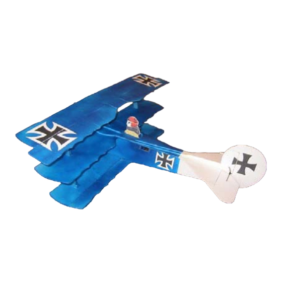
Wingspan: 27 in
Wing Area: 276 sq in
Kit #DMRC0001D by:
Digital Millwork
8038 E. Brown Rd
Lowell, AR 72745
www.digitalmillwork.com
Sales@digitalmillwork.com
Little Baron
Indoor Fokker Dr I Tri-plane
Construction Manual
Designed by Peter Stapleton
'pmjass' on rcgroups.com
Little Baron RC Groups Thread
Length: 23 in
Flying weight: 6 to 8oz
© 2005 Digital Millwork
Advertisement

Summary of Contents for Digital Millwork Little Baron Fokker DR I
- Page 1 ‘pmjass’ on rcgroups.com Little Baron RC Groups Thread Wingspan: 27 in Length: 23 in Wing Area: 276 sq in Flying weight: 6 to 8oz Kit #DMRC0001D by: Digital Millwork 8038 E. Brown Rd Lowell, AR 72745 www.digitalmillwork.com Sales@digitalmillwork.com © 2005 Digital Millwork...
- Page 2 Digital Millwork Deluxe kits are very complete requiring only your radio, battery, and chosen propulsion system. Items included in kit: CNC Cut white Depron Foam, balsa and ply parts Carbon Fiber pushrods Control horns Carbon fiber rods for undercarriage construction...
- Page 3 Note: This is Little Baron manual version 1.0. Before beginning construction, you should check for an updated manual on the Digital Millwork website: http://www.digitalmillwork.com Manual Revision History: 3/15/05 ver 0.9 to version 1.0 o Added brushed motor information to specs o Changed recommended starting C.G.
- Page 4 Indoor Fokker DR I Construction: Step 1: Upper Fuselage Wing and Fuse assembly o On a flat surface, glue middle wing to fuselage front and fuselage rear. Note: Painting your Fokker This manual does not detail the painting of your aircraft as everyone has their own preferences. You may want to paint the parts before or during assembly or you may want to wait till it’s complete.
- Page 5 Hinge Elevators to stabilizer o Hinge the two elevator pieces to the stabilizer. The elevator control horn slot should be on the left elevator when looking Control horn slot on left side from the top rear of the elevator assembly. To use tape hinges, sand a 45 degree angle on the bottom side of the front of the two elevator pieces.
- Page 6 Step 2: Lower Fuselage The kit comes with mounts for 4 different styles of motors: IPS Stick Mount Spindle Mount Rear Flange Mount Front collar mount See step 9 for mount details o Choose the mounting type that fits your motor and test fit it and your motor in the fuselage profile.
- Page 7 The elevator control horn cutout will be on the right side o Turn the upper fuselage assembly when looking at assembly from rear when upside down. completed in step 1 upside down. o Mark the center lengthwise of the medium (2 3/4”) plywood undercarriage mount.
- Page 8 o Hold the profile in place and mark where the undercarriage mount will be and cut out profile to clear mount. o If you are not using GWS pico servos, check servo fit. If you need to enlarge the servo mounting hole do so now and modify the plywood servo reinforcement or make a new one from balsa to fit your servos.
- Page 9 o Glue the fuselage profile into place. Tabs in the fuselage profile will fit into slots in the upper fuselage assembly. Use your square to set the fuselage profile perpendicular to the upper fuselage/wing assembly.
- Page 10 Step 3: Lower Wing Preparation o Use a pen or Sharpie to lightly mark the centerline on both the upper and lower surface of the bottom wing. (the upper surface has the strut locations marked.) o Glue the balsa leading edge to the front of the upper surface of the lower wing.
- Page 11 Glue the long set of plywood aileron linkage horns (1 ½” x 3mm) into place on the bottom ailerons. (The bottom ailerons are the smaller ones) o Using tape hinges as in Step 1 or your preferred hinging method, attach the lower ailerons to the bottom wing.
- Page 12 Step 4: Lower wing attachment o Align the fuselage profile on the bottom wing and check fit. o Push the two long struts carefully through the center wing/fuselage assembly. (The struts lean forward) o Using centerline drawn on lower wing in previous step, glue lower wing to bottom of fuselage profile.
- Page 13 Step 5: Fuselage top assembly o Align in center of upper fuselage and glue the cockpit cutout on top of the upper fuselage. Be sure the center strut hole is lined up. o Glue the gun deck in front of the cockpit.
- Page 14 Step 6: Upper Wing Preparation o Glue the balsa leading edge to the top front of the upper wing. Round the leading edge with sandpaper if desired. . (The top of the wing does not have the strut locations marked on it). o Flip the wing over and glue three foam strut supports over the marked rectangles.
- Page 15 o Glue the short set of aileron horns (13/16”) into place on the top ailerons. o Using tape hinges as in Step 1 or your desired hinging method, attach the ailerons to the top wing. Optional: You may want to apply a layer of packing tape on each side of the ailerons to stiffen up the control surface, particularly if you expect to fly outside in light wind.
- Page 16 Step 7: Top Wing attachment o Glue the top wing into place on the struts making sure it is parallel with the bottom and middle wings.
- Page 17 Step 8: Rudder Note: The supplied plywood control horns are 2 pieces to provide more surface area in contact with the foam control surfaces. Slide the two pieces together and glue with CA, then glue into place in the slots provided in the control surface. o Using tape hinges as in step 1 or your preferred method, hinge the rudder to the vertical stabilizer.
- Page 18 Step 9: Motor Mount o If you had to cut the fuselage profile to fit your motor in Step 2, mark and cut the front fuselage doublers to fit. Two sets of doublers are provided, the solid ones are used for a front collar type engine mount and the cutout ones are for mounts using the IPS stick (IPS,...
- Page 19 Spindle Mount o Glue the cutout fuselage doublers into place on either side of the fuselage. o Fit the spindle mount adaptors onto the IPS mount stick and place your motor in the adaptors. o Test fit the IPS mount stick into place and mark the length needed to properly position your motor so that the...
- Page 20 Rear Flange Mount o Glue the cutout fuselage doublers into place on either side of the fuselage. o Slide the rear mount plywood plate onto the IPS mount stick and test fit the stick into the fuselage. o Slide the mount plate back until your motor fits properly and mark the IPS mount stick at the front of the mounting...
- Page 21 Front Collar Mount o Glue the solid fuselage doublers onto either side of the fuselage. o Test fit your motor in the hole provided in the plywood collar mount and enlarge if needed. o Make any fuselage cutout needed to clear motor. o Glue the Mount to the front of the fuselage allowing for a slight bit of right thrust...
- Page 22 Step 10: Upper/Lower Aileron Linkage o Tape the upper and lower ailerons in their neutral position. o Using a 3/4” piece of the supplied 10” long heat shrink tubing, attach one of the supplied z bend wires to each of the 6 1/4” 1.5mm Carbon Fiber aileron rods.
- Page 23 Step 11: Control Horns o Install the supplied plywood control horns in the slots cut in the elevator and lower ailerons. The control horns are 2 pieces to provide support over a wider area of the control surface. Glue the upper support piece into the control horn and glue horn into slot in control surface.
- Page 24 Step 12: Undercarriage o Use a 1/8” drill bit or punch to extend the holes for the landing gear in the ply reinforcement on the bottom of the lower wing on through the foam and balsa of the lower wing so the 2mm Carbon Fiber landing gear rod can be pushed through the wing.
- Page 25 o Place supplied wheels on the 1mm rod and hold in place by shrinking a small piece of the supplied 1/2 “ long small diameter heat shrink tubing on the end of the axle. o Set plane on wheels and adjust so aircraft sits level, and then glue the 2mm rods to all plywood reinforcements.
- Page 26 Step 13: Servo Installation o Install the aileron servo in the fuselage front of the lower wing using hot glue. o Install the rudder and elevator servos in the fuselage below the cockpit using hot glue. The rudder servo should be installed with the control arm facing the right side of the plane and on the...
- Page 27 o Power up servo’s and make sure they are in their center position. o Build two aileron pushrods using the supplied 2” 1.5 mm CF rod, z bends, and shrink wrap as outlined in step 11 above. o Build and install Elevator pushrod using the 8”...
- Page 28 o Build and install Rudder pushrod using the 8 3/4” 1.5mm CF rod.
- Page 29 Step 14: Radio, Battery and ESC Installation o Temporarily mount your receiver, battery, and ESC on fuselage using tape. Adjust their position to get your center of gravity where you want it. The suggested starting point for the C.G. is 1 1/8” back from the leading edge of the middle wing. Once you’ve located the proper position for the battery and receiver, mount the receiver and ESC using hot glue or Velcro.
- Page 30 If you’d like to kit an aircraft of your own design or cut a quantity of an aircraft for a club build function, Digital Millwork can help with precision CNC cutting of foam, balsa, and ply components at very reasonable costs. We will also consider kitting and...
- Page 31 Insignia: These Insignia as well as outline versions are also in the insignia directory on the CD.
- Page 33 33 33...
- Page 35 Machine Guns – Cut out and roll into tube.
Need help?
Do you have a question about the Little Baron Fokker DR I and is the answer not in the manual?
Questions and answers