Advertisement
Quick Links
Advertisement

Subscribe to Our Youtube Channel
Related Manuals for SoarTronic IOIO UART


Summary of Contents for SoarTronic IOIO UART
- Page 1 Soartronic IOIO UART interface v2e assembly manual www.soartronic.com...
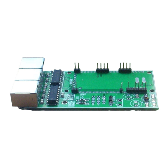
- Page 2 This manual is for both IOIO v1 IOIO-OTG Components assembled should look like this: components marked with arrows have polarity, and must be soldered as shown in the picture. Also make sure that the holes of micro-ships marked with YELLOW arrows are as shown on the picture. BLUE arrows show places for extra components, which may be used to filter the 5V output from IOIO-OTG card.
- Page 3 You should connect the points marked with white circles on back side of the Soartronic IOIO UART interface board. One circle is marked with RED arrow for an example. We also recommend to connect the corners for IOIO card...
- Page 4 You should connect the points marked with white circles on top side of the Soartronic IOIO UART interface board. One circle is marked with RED arrow for an example. We also recommend to connect the corners for IOIO card...
- Page 5 In earlier shown example pictures surface mounted capacitors were used. If you have trough hole components, your board will look more like this: And this: Note also on the above picture the orientation of the larger capacitors, they have polarity. The small ones do not.
- Page 6 JP3 connects UART_1 RJ45 connector pin6 with the 5V line of the Soartronic IOIO UART Interface and the IOIO card. This can be used to power the IOIO card, or to feed 5V out of the card. If powered from outside with 5V THE...
- Page 7 About the use of JP1: If you have FLARM that has already 12V supply, and you want to keep that instead of feeding 12V from Soartronic IOIO interface, do not connect JP1. If your FLARM has separate 12V/GND wires connected, you just connect the Flarm port to the FLARM dataport with straight RJ cable.
- Page 8 About the use of JP2 JP2 connects 12V to the UART 1 RJ45 connector. JP2 is use to connect 12V to the RJ45 connector according to IGC standard. This way you can connect RS232 communication and 12V power to devices like Volkslogger, and some Colibri loggers.
- Page 9 If 5 V is generated by the device that is connected to this pin 6, it can be used by the IOIO card instead of its own 5V regulated from the 12V supply voltage. In that case 12V should NOT be connected to the Soartronic IOIO UART interface!
- Page 10 Diode direction print is missing from many UART interface boards, since it was placed too close to copper. The white arrows in his picture shows how to solder the diodes: (the holes next to the two diodes is for fixing wires connected to UART2 and UART3 using narrow wire straps.)
- Page 11 Place pin-headers for the first generation IOIO card as shown in images below. THIS IS IMPORTANT!!! For first generation IOIO make sure the voltage and GND connection pins are exactly as shown here, and as marked with white circles One pin that is used to connect voltage measurement to 12V line is missing from these pictures! Place for that pin is marked with RED arrow, and it is marked with white circle.
- Page 12 Place pin-headers for IOIO-OTG card as shown in images below. THIS IS IMPORTANT!!! For IOIO OTG make sure the voltage and GND connection pins are exactly as shown here, and as marked with white circles The pin that is used to connect voltage measurement to 12V line is missing from these pictures! Place for that pin is marked with RED arrow, and it is marked with white circle on the circuit-board.
- Page 13 Just for an example: This picture shows jumpers for - Connecting 12V line to FLARM RJ45 cables - Connecting jumpers for use with IOIO-OTG >> In this example FLARM is powered from Soartronic interface card, and IOIO-OTG is used. >>...
- Page 14 IOIO UART interface connections: A) UART 0, FLARM splitter. These two RJ45 IGC standard ports are connected together as a “RJ45 splitter”. Port market “FLARM” can communicate with FLARM. “DISPLAY” port can be used to forward FLARM communication to other devices like display units, variometers, etc.
Need help?
Do you have a question about the IOIO UART and is the answer not in the manual?
Questions and answers