Table of Contents
Advertisement
Quick Links
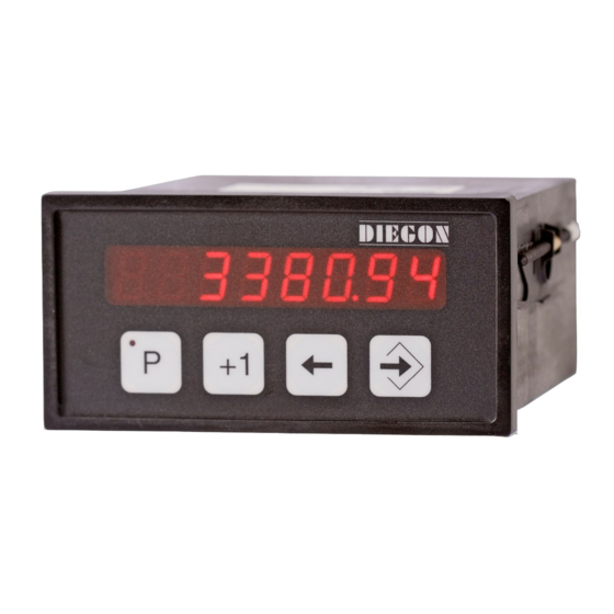
Manual AP80
Display Controller
• 8 Digit display in DIN-enclosure 144 X 72 mm
• Supply voltage 10 – 35V DC
• All in- and outputs optically isolated
• Input for absolute SSI encoders, incremental en-
coders, parallel encoders and Start/Stop sensors
• CAN-bus, RS232, RS422/RS485
• 6 Digital inputs and 9 digital outputs
• 24 Programmable cams / 9 outputs
• 48 Programmable nominal values
• Dynamic cam-adjustment (cycletime 250µ µ µ µ S)
• Programmable analog output (16 bit)
• Linearization function
• Datamodule for 24 in- and 24 outputs
• Datamodule for 32 (tri-state) outputs
Advertisement
Table of Contents

Summary of Contents for DIEGON AP80
- Page 1 Manual AP80 Display Controller • 8 Digit display in DIN-enclosure 144 X 72 mm • Supply voltage 10 – 35V DC • All in- and outputs optically isolated • Input for absolute SSI encoders, incremental en- coders, parallel encoders and Start/Stop sensors •...
-
Page 2: Table Of Contents
Manual AP80 2016 V02. For software version V6.03. Subject to change without notice. Table of contents 1 Introduction ....................6 ..........................6 ENERAL ...................... 7 MPORTANT INFORMATION EMC ............................7 ..........................7 EFINITIONS 1.4.1 Display units AWE ......................7 1.4.2 Parameter number ...................... - Page 3 Manual AP80 2016 V02. For software version V6.03. Subject to change without notice. 4.11.2 Justage Using the input K0 ................... 32 4.11.3 Justage using service parameter P[207] ..............32 4.11.4 Justage using front keys ....................33 4.11.5 Justage using input 1…6 ....................33 4.12 CAN-...
- Page 4 ) ................... 103 ATA OUTPUT FEMALE 6.18 D (37P ) ................... 104 ATA OUTPUT FEMALE 7 Technical specifications ................. 105 ........................105 PECIFICATIONS ..........................108 YPEKEY ..................... 108 YPEKEY HUMBWHEEL SETS AP80 ......................109 IMENSIONS EMC-B01 ..............110 IMENSIONS BRACKET TYPE...
- Page 5 Manual AP80 2016 V02. For software version V6.03. Subject to change without notice. APD- ..............111 IMENSIONS THUMBWHEEL SWITCHES CDS-B01..............112 IMENSIONS PROTECTIVE HOOD TYPE...
-
Page 6: Introduction
With the 24 programmable cams several functions can be realized like limit detection. Another feature of the AP80 is the memory for the nominal values. The 48 programmable values can be used to determine the positions of the cams. Up to 4 values can be read from external thumbwheel switches. These values can be used as positions for the cams or as preset values. -
Page 7: Important Information
AP80. If through a failure or fault the AP80 an endangering of persons or damage to plant is possible, this must be prevented using additional safety measures. -
Page 8: Notation
Manual AP80 2016 V02. For software version V6.03. Subject to change without notice. 1.4.3 Notation Values can be displayed in different notations like binary or hexadecimal. The character behind the value shows in which notation the value is represented: 100D... -
Page 9: Operation
Manual AP80 2016 V02. For software version V6.03. Subject to change without notice. 2 Operation 2.1 Key functions [P] key - Cycle through monitoring displays - Activate programming mode (in combination with other keys) [+1] key - View type number... -
Page 10: Key Functions In Programming Mode
Manual AP80 2016 V02. For software version V6.03. Subject to change without notice. 2.2 Key functions in programming mode [P] key - one step back in menu - discontinue programming mode - discontinue changing nominal values/parameters (edit mode) - LED is on when programming mode is active... -
Page 11: Display Functions
Manual AP80 2016 V02. For software version V6.03. Subject to change without notice. 2.3 Display functions 2.3.1 Status functions Power on Appr. 1sec. Operating (normal) mode 2.3.2 Error messages There are two groups of errors: Parameter errors (error numbers 0…499, preceeded by a “P”) -
Page 12: Survey Of Error Messages
Manual AP80 2016 V02. For software version V6.03. Subject to change without notice. 2.3.3 Survey of error messages Error messages: 000...499 Parameter error is displayed as PXXX on the display. 700 = Reference value P[003] >= Counting range P[004] 701 = Adjustment value SSI P[005] >= Counting range or Adjustment SSI P[005] <... - Page 13 Manual AP80 2016 V02. For software version V6.03. Subject to change without notice. Error meldingen linearisatie (xx = P1 …P30) 9xx = Linearisatie Xn <= Xn-1 940 = Linearisatie (modus 1 of 2) X1 <> 0 941 = Linearisatie modus 1) Y1 <> 0 Error messages for cams (latst 2 digits = cam number) 1001…1024...
-
Page 14: Programming
Manual AP80 2016 V02. For software version V6.03. Subject to change without notice. 3 Programming There are three different modes of operation: Automatic mode Programming mode for nominal values Programming mode for parameters Automatic mode Programming mode Programming mode Nominal values... -
Page 15: Monitor Function
Manual AP80 2016 V02. For software version V6.03. Subject to change without notice. 3.1.1 Monitor function In automatic mode different variables can be displayed. By using the [P] key one can cycle through the different pages: Actual position Actual velocity... -
Page 16: Displaying The Type Number
Manual AP80 2016 V02. For software version V6.03. Subject to change without notice. 3.1.2 Displaying the type number Automatic mode Type 3.1.3 Displaying the software-version Automatic mode Standard software Keep pressed Custom software... -
Page 17: Status In- And Outputs
Manual AP80 2016 V02. For software version V6.03. Subject to change without notice. 3.1.4 Status in- and outputs Automatic mode Inputs Outputs Outputs 1 = input-1 7 = output-1 17 = Hold/Reset active 2 = input-2 8 = output -2... -
Page 18: Changing Nominal Values
Manual AP80 2016 V02. For software version V6.03. Subject to change without notice. 3.2 Changing nominal values Access to nominal values Automatic mode Then Select nominal values Nominal value number Exit programming mode After 2 s Nominal value number +1... -
Page 19: Changing Parameters
Manual AP80 2016 V02. For software version V6.03. Subject to change without notice. 3.3 Changing parameters 3.3.1 Menus The parameters are displayed in different menus and submenus: 1 ConFiG 10 D-SEt 2 ActuAL 10.1 ConF. 2.1 Cnt. 10.2 SEt-1 2.2 SSI 10.3 SEt-2... -
Page 20: Input Parameters
Manual AP80 2016 V02. For software version V6.03. Subject to change without notice. 3.3.2 Input parameters Access parameters Automatic mode Then Menu selection Menu Exit programming mode Menu item +1 To submenu/parameter number Menu Submenu selection Submenu Back to menu... -
Page 21: Functions
2016 V02. For software version V6.03. Subject to change without notice. 4 Functions 4.1 Basic function The basic function of the AP80 is programmed at P[200]. Factory setting P[200] = 0, where the sensor-value will be shown on the dis- play. - Page 22 Manual AP80 2016 V02. For software version V6.03. Subject to change without notice. Hold/Reset start/stop H and Hold/Reset start/stop L (P[200] = 3 or 4) Hold/Reset start and stop using input (1…6) high and low active start stop start stop...
- Page 23 Manual AP80 2016 V02. For software version V6.03. Subject to change without notice. Hold/Reset start/stop H (P[200] = 6) Hold/Reset start and stop using input 1…6 falling flank start stop countervalue td = countervalue display...
-
Page 24: Actual Position
Manual AP80 2016 V02. For software version V6.03. Subject to change without notice. 4.2 Actual position The actual position shown on the display is depending on the selected sensor input (P[201]) and several parameters. Counterinput and internal frequency: Actual position = Counter x FL x dir x... -
Page 25: Multiplicator
Through P[203] it is possible to adjust the decimal point. 4.5 Power failure protection If P[206] = 1 then the actual position of the AP80 will be stored in EEPROM when power is shut down. After power up this value will be restored. -
Page 26: Edge Multiplication (Counter Input)
Manual AP80 2016 V02. For software version V6.03. Subject to change without notice. 4.6 Edge multiplication (counter input) There are two possibilities for the counter input: V-signal x4: edge multiplication x4, 90º shifted encodersignals. count S-signal x2: edge multiplication x2, encoder signal with directional signal. -
Page 27: Preset Using Input K0
Manual AP80 2016 V02. For software version V6.03. Subject to change without notice. 4.7.1 Preset using input K0 The function preset is used to set the actual value to a programmed value, stored in P[003], P[204] or 102] or external thumbwheel-1. -
Page 28: Counting Range (Counter Input And Internal Frequency)
Manual AP80 2016 V02. For software version V6.03. Subject to change without notice. 4.8 Counting range (counter input and internal frequency) The counting range used by the counter can be limited when using the coun- ter input or the internal frequency (P[201] = 0 or 2). The counting range can be set either by parameter or nominal value. -
Page 29: Set Counting Range By Nominal Value
Normally the most significant bit (MSB) is transmitted first by the encoder. The number of clock pulses determine the number of bits that will be read by the AP80. Basically this will be the number of bits that the encoder transmits. Example: The SSI-encoder has a resolution of 4096 positions per revolution and 4096 coded revolutions. -
Page 30: Ssi Monitoring
Manual AP80 2016 V02. For software version V6.03. Subject to change without notice. Example: The SSI-encoder has 16 singleturn bits (65535 positions/rev.) and 14 multiturn bits (16384 coded revolutions). The resolution should be 8192 positions/rev. = 13 bit. The number of revolutions should not be changed (remains 14). -
Page 31: Output "Ssi Error
Manual AP80 2016 V02. For software version V6.03. Subject to change without notice. 4.10.1 Output "SSI error" It is possible to create a SSI-error signal using one of the outputs 1..6: Output SSI error Output-x = option "2 SSI error"... -
Page 32: Justage Using The Input K0
K0 detects a rising edge, possibly combined with a reference coarse signal ([P213]). For option 5 and 6 this value is given by the external data input. (AP80/81- CxP). If through parameter [P213] reference coarse has been activated ([P213] <>... -
Page 33: Justage Using Front Keys
Manual AP80 2016 V02. For software version V6.03. Subject to change without notice. 4.11.4 Justage using front keys The function preset the absolute position can be executed with the key com- bination [P] + [Enter]. Holding down the [Enter] key and push the [P] key once. Then the actual posi- tion is preset to the value of P[005]. -
Page 34: Can-Bus
3.1.1), where “0” = no error and “1” = bus off. 4.12.1 AP-Link Using the CAN bus it is possible to sent the actual position and velocity in just one message to one or more other AP80’s (AP40,s). Example: Encoder... - Page 35 0 or 1 0 or 1 In this example the first AP80 (1) is sending the actual position and velocity to adress 1 with 500 kbit/s (dataframe COB-ID 385…511). AP80 (2) and (3) receive this data as actual position and velocity.
-
Page 36: Start/Stop Sensor
Display counting range P[103] = 4.12.2 Start/Stop sensor The AP80 sends a start signal to the sensor and then waits for the stop signal to return from the sensor. The time between the start and stop sig- nal is an measure for the sensor (magnet) position. -
Page 37: Ascii Protocol
2016 V02. For software version V6.03. Subject to change without notice. 4.13 ASCII protocol The serial ports of the AP80, both RS232 and RS422/485, are able to work with the ASCII protocol, however not at the same time. Using the ASCII protocol, actual values can be read, parameters and nominal values can be stored and read, the status of the digital inputs and outputs can be monitored etc. -
Page 38: General
Manual AP80 2016 V02. For software version V6.03. Subject to change without notice. 4.13.2 General Through the ASCII protocol it is possible to communicate with the AP80 Send: Data from PC, PLC AP80 Receive: Data from AP80 PC, PLC AP80... -
Page 39: Functions
The AP80 with the unit Id number is selected, all consecutive com- mands are relevant for this unit. An AP80 with unit Id number 0 will always respond. This is the reason that only one unit is allowed to have unit Id number 0. - Page 40 Manual AP80 2016 V02. For software version V6.03. Subject to change without notice. receive: r3 xxxxxxxx transmitting parameter: none Read status inputs send: receive: ri xxx transmitting parameter: none B0 = input K0 B1 = input-1 B2 = input-2 B3 = input-3...
- Page 41 Manual AP80 2016 V02. For software version V6.03. Subject to change without notice. B8 = output-9 Read status input K1, K2 and K0 send: receive: rk x transmitting parameter: none B0 = K0 B1 = K1 or counting direction B2 = K2 or counting pulse Write outputs (only valid for outputs with “ASCII protocol”...
- Page 42 Manual AP80 2016 V02. For software version V6.03. Subject to change without notice. Read status data input send: receive: ra xxxxxxxx transmitting parameter: none Example: ra 1320 gives the following answer: 1320 528H, 0101 0010 1000 B Read status data output...
- Page 43 Manual AP80 2016 V02. For software version V6.03. Subject to change without notice. Read parameter send: rp xxx receive: rp xxxxxxxx transmitting parameter : parameter number Example reading parameter P[004] send: rp 4 answer: rp 4 10000 write parameter (only EEPROM)
- Page 44 Manual AP80 2016 V02. For software version V6.03. Subject to change without notice. Write nominal value (RAM + EEPROM) send: ws xx xxxxxxxx receive: ws xx xxxxxxxx transmitting parameter: nominal value number and nominal value Example writing nominal value 22 with value 195200...
- Page 45 Manual AP80 2016 V02. For software version V6.03. Subject to change without notice. Read error number send: receive: rf xxxx transmitting parameter: none When -1 returns no error is present. Example: send: answer: (SSI error) rf 800 answer: (no error) rf –1...
-
Page 46: Error Messages
(no errors) bp -1 answer: (error parameter 20) 4.13.4 Error messages In case of an error the AP80 will sent an error message followed by an error number. overview error messages er 1 = parity error er 2 = frame error... -
Page 47: Analog Output
2016 V02. For software version V6.03. Subject to change without notice. 4.14 Analog output The AP80 has an optional, galvanic isolated analog output. Using parameter P[388] it is possible to choose between a current output or a voltage out- put.The analog output can be used to give out the actual position or velocity (see parameter P[383]). -
Page 48: Current Output
Manual AP80 2016 V02. For software version V6.03. Subject to change without notice. 4.16 Current output The current output has a resolution of 610 µA and is programmable through P[084] … P[087]. P[084] = Imin [mA] (input in 0,0001mA units) -
Page 49: Example Programming Voltage Output
Manual AP80 2016 V02. For software version V6.03. Subject to change without notice. 4.17 Example programming voltage output > 0,01 mm units > actual position at +9V should be -850,00 mm > actual position at -8V should be 1100,00 mm... -
Page 50: Cams
Manual AP80 2016 V02. For software version V6.03. Subject to change without notice. 4.18 Cams 4.18.1 General The AP80 has a maximum of 24 programmable cams divided over a maxi- mum of 9 outputs. Programmable functions: • Type 1. Cam with start- and end-value 2. -
Page 51: Greater Than Or Equal To Limit Value
Manual AP80 2016 V02. For software version V6.03. Subject to change without notice. 4.18.3 Greater than or equal to limit value Only one limit value needs to be programmed. Limitvalue = 100 100 101 Hysteresis = 2 Hysteresis = 0 4.18.4 Smaller than or equal to limit value... -
Page 52: Dynamic Cams
Manual AP80 2016 V02. For software version V6.03. Subject to change without notice. 4.18.5 Dynamic cams To compensate for actions with a static time, for example the switch time of a valve, it is possible to program a time for each output individually. The cams will be shifted according to this programmed time. -
Page 53: Start/Stop Cam
Manual AP80 2016 V02. For software version V6.03. Subject to change without notice. 4.18.6 Start/stop cam The outputs for the cams can be enabled or disabled, if for one of the inputs 1..6 the function start/stop cams has been chosen. -
Page 54: Relative Cams
Manual AP80 2016 V02. For software version V6.03. Subject to change without notice. 4.18.8 Relative cams When using relative cams it is possible to configure simple positioning sys- tems. The cams will switch based on the difference between the actual posi- tion and an external value. - Page 55 Manual AP80 2016 V02. For software version V6.03. Subject to change without notice. Nom = External data Act = Actual position Nom-Act < 0 Nom-Act = 0 Nom-Act > 0 Backward Forward Fast backward Fast forward In position Signal Outp.
-
Page 56: Data Input
Possible output data is the actual position or actual velocity. The data of mul- tiple AP80’s can be set to busmode and therefore all be read by a PLC. The store-function will lock the data during reading and the enable-function will enable the data. -
Page 57: Input Enable
Manual AP80 2016 V02. For software version V6.03. Subject to change without notice. 4.20.3 Input enable Through the inputs one can activate the “enable”- signal. The signal activates or deactivates the data output. If none of the inputs has been assigned, the data output is always active. -
Page 58: External Thumbwheel Sets
4.21 External thumbwheel sets 4.21.1 General Up to 4 external thumbwheel sets can be connected to the AP80. The data is read by the RS422 serial interface (ser-2) en can be configured separate. The thumbwheel value can also be read by the monitor function in auto mode. -
Page 59: Parameter Settings
Manual AP80 2016 V02. For software version V6.03. Subject to change without notice. 4.21.3 Parameter settings P[245] must be set to 0 (if RS422/RS485 ser-2 is not active) Parameter P[222] determines the number of thumbwheel sets that will be read. -
Page 60: Linearization
Manual AP80 2016 V02. For software version V6.03. Subject to change without notice. 4.22 Linearization The linearization function allows to display and process nonlinear motions. The actual display position (sensor) position or actual velocity is converted into an additional value “Actual linearization”. This additional value can serve as a source for the cams function and analog output. -
Page 61: Mode 0 "4-Quadrant
Manual AP80 2016 V02. For software version V6.03. Subject to change without notice. 4.22.1 mode 0 “4-Quadrant” This is the standard mode wich can build every possible curve. Both the X- axis and the Y-axis may contain negative values. Condition: P1-X <... -
Page 62: Mode 1 "Mirror Y-Axis
Manual AP80 2016 V02. For software version V6.03. Subject to change without notice. 4.22.2 mode 1 “Mirror Y-axis” In this mode, the entered curve is mirrored and copied over the Y-axis, so that this curve is the same for the negative X-axis values. Q1 is the entered curve. -
Page 63: Parameters
Manual AP80 2016 V02. For software version V6.03. Subject to change without notice. 5 Parameters General lay-out: PAR. PAR Nr: Possible values (bold is the standard value) Basic description Description of possible values 5.1 Menu 1 Config PAR: 1.0.1 P[200] 0 …... - Page 64 0 = not active 1 = active PAR: 1.0.9 P[207] 0 … 123 Service functions Only possible to activate through keyboard AP80 0 = not active 123 = set default parameters (automatically reset to 0) PAR: 1.0.10 P[208] 0 … 2 Default monitor function Determines the default which is visible after start-up.
-
Page 65: Menu 2 Actual
Manual AP80 2016 V02. For software version V6.03. Subject to change without notice. 5.2 Menu 2 Actual 5.2.1 Submenu 2.1 Counter PAR: 2.1.1 P[210] 0 … 1 Signal type and edge multiplication "S-signal X2": K2 is counter and K1 is direction... -
Page 66: Submenu 2.2 Ssi
Manual AP80 2016 V02. For software version V6.03. Subject to change without notice. PAR: 2.1.7 P[209] 0 … 2 Counting direction for setting reference value 0 = independant from direction 1 = when counting in positive direction 2 = when counting in negative direction PAR: 2.1.8 P[003]... - Page 67 Manual AP80 2016 V02. For software version V6.03. Subject to change without notice. PAR: 2.2.3 P[216] 0 … 24 … 30 Number of SSI clockpulses PAR: 2.2.4 P[217] 0 … 24 … 30 Number of SSI databits PAR: 2.2.5 P[000] 0 …...
- Page 68 Manual AP80 2016 V02. For software version V6.03. Subject to change without notice. PAR: 2.2.9 P[209] 0 … 2 Counting direction adjustment 0 = independant from direction 1 = when counting in positive direction 2 = when counting in negative direction PAR: 2.2.10 P[002]...
-
Page 69: Submenu 2.3 Internal Frequency
Manual AP80 2016 V02. For software version V6.03. Subject to change without notice. 5.2.3 Submenu 2.3 Internal frequency PAR: 2.3.1 P[224] 0 … 3 Timebasis 0 = 78,125 kHz 1 = 625 kHz 2 = 5 MHz 3 = 10 MHz PAR: 2.3.2... -
Page 70: Submenu 2.4 Parallel
Manual AP80 2016 V02. For software version V6.03. Subject to change without notice. PAR: 2.3.7 P[209] 0 … 2 Counting direction for setting reference value 0 = independant from direction 1 = upwards counting 2 = downwards counting PAR: 2.3.8 P[003] -9999999 …... -
Page 71: Submenu 2.5 Can Ap-Link
Manual AP80 2016 V02. For software version V6.03. Subject to change without notice. PAR: 2.4.4 P[000] 0 … 10000 … 16777215 Multiplicator numerator XXXXXXXX PAR: 2.4.5 P[001] 0 … 10000 … 16777215 Multiplicator denominator XXXXXXXX PAR: 2.4.6 P[002] -9999999 … 0 … 99999999... -
Page 72: Submenu 2.6 Start/Stop
Manual AP80 2016 V02. For software version V6.03. Subject to change without notice. 5.2.6 Submenu 2.6 Start/Stop PAR: 2.6.1 P[115] 0 … 280000 .. 999999 Gradient Actual signalspeed sensor internal in m/s (0 = 2800.00 m/s) XXXX.XX (m/s) PAR: 2.6.2 P[118] 0 …... -
Page 73: Menu 3 Can-Bus
Manual AP80 2016 V02. For software version V6.03. Subject to change without notice. PAR: 2.6.7 P[213] 0 … 2 Reference coarse 0 = no function 1 = high signal 2 = low signal PAR: 2.6.8 P[209] 0 … 2 Counting direction adjustment... -
Page 74: Submenu 3.2 Obj1/Pdo1 In
Manual AP80 2016 V02. For software version V6.03. Subject to change without notice. 5.5 Submenu 3.2 Obj1/PDO1 In PAR: 3.2.1 P[089] 0 … 1 … 127 CAN adress Obj/PDO1 In PAR: 3.2.2 P[229] 0 … 1 Function Obj/PDO1 In 0 = not active 1 = AP-Link (reading actual position and velocity) 5.6 Submenu 3.3 Obj1/PDO1 Out... -
Page 75: Menu 4 Serial
Manual AP80 2016 V02. For software version V6.03. Subject to change without notice. 5.7 Menu 4 Serial 5.7.1 Submenu 4.1 Config PAR: 4.1.1 P[236] 0 … 31 Unit adress 5.7.2 Submenu 4.2 Ser-1 (RS232) PAR: 4.2.1 P[237] 0 … 1 … 4... -
Page 76: Submenu 4.3 Ser-2 (Rs422/485)
Manual AP80 2016 V02. For software version V6.03. Subject to change without notice. 5.7.3 Submenu 4.3 Ser-2 (RS422/485) PAR: 4.3.1 P[242] 0 …1 … 4 Baudrate 0 = 9600 1 = 19200 2 = 28800 3 = 38400 4 = 57600 PAR: 4.3.2 P[243]... -
Page 77: Menu 5 Input
Manual AP80 2016 V02. For software version V6.03. Subject to change without notice. 5.8 Menu 5 Input INPUT-1 PAR: 5.0.1 P[249] 0 … 16 Function input-1 0 = no function 1 = coarse 2 = store 3 = enable 4 = error reset SSI... - Page 78 Manual AP80 2016 V02. For software version V6.03. Subject to change without notice. INPUT-5 PAR: 5.0.5 P[253] 0 … 16 Function input-5 XX (see input-1) INPUT-6 PAR: 5.0.6 P[254] 0 … 16 Function input-6 XX (see input-1)
-
Page 79: Menu 6 Output
Manual AP80 2016 V02. For software version V6.03. Subject to change without notice. 5.9 Menu 6 Output 5.9.1 Submenu 6.1 – 6.9 Op1…9 OUTPUT 1…9 PAR: 6.x.1 P[389]…P[397] 0 … 8 Function output-1 0 = cam 1 = cam inverted... -
Page 80: Menu 7 Data
Manual AP80 2016 V02. For software version V6.03. Subject to change without notice. 5.10 Menu 7 Data 5.10.1 Submenu 7.1 Data in PAR: 7.1.1 P[379] 0 … 24 Number of active bits PAR: 7.1.2 P[380] 0 … 5 Data input code... -
Page 81: Submenu 7.2 Data Out
2 = minus-sign on pin 25/35 L = sign active PAR: 7.2.3 P[386] 0 … 2 Data ready output AP80-XXP data valid on pin 25 or 12 AP80-XXF data valid on pin 35 or 16 0 = no function 1 = data valid on pin 25/35 2 = data valid on pin 12/16 PAR: 7.2.4 P[387]... -
Page 82: Menu 8 Analog
Manual AP80 2016 V02. For software version V6.03. Subject to change without notice. 5.11 Menu 8 Analog 5.11.1 Submenu 8.1 Config PAR: 8.1.1 P[388] 0 … 2 Selection DA output 0 = inactive 1 = voltage 2 = current PAR: 8.1.2 P[383] 0 …... -
Page 83: Submenu 8.3 Da-I (Current)
Manual AP80 2016 V02. For software version V6.03. Subject to change without notice. 5.11.3 Submenu 8.3 DA-I (current) DA PAR 8.2.1…8.2.4 = 0: DA not active PAR: 8.3.1 P[084] -200000 … 199999 Imin DA -XX.XXXX (mA) PAR: 8.3.2 P[085] -199999 … 200000 Imax DA -XX.XXXX (mA) -
Page 84: Menu 9 Cam
Manual AP80 2016 V02. For software version V6.03. Subject to change without notice. 5.12 Menu 9 Cam 5.12.1 Submenu 9.1 … 9.24 CA1…24 CAM-1…24 PAR: 9.x.1 P[256]...P[279] 0 … 3 Cam function 0 = no function 1 = range 2 = actual position >= limit value 3 = actual position <= limit value... -
Page 85: External Thumbwheel Sets
Manual AP80 2016 V02. For software version V6.03. Subject to change without notice. PAR: 9.x.6 P[031]…P[054] -9999999 … 2000 …99999999 Cam end -XXXXXXX PAR: 9.x.7 P[055]…P[078] 0 … 999999 Hysteresis cam XXXXXX PAR: 9.x.8 P[352]…P[375] 0 … 9 Assign cam to output 0 = no output 1…9 = output 1-9... -
Page 86: Submenu 10.2
Manual AP80 2016 V02. For software version V6.03. Subject to change without notice. 5.13.2 Submenu 10.2 …10.4 Set-1...4 PAR: 10.x.1 P[110]…P[113] 0 … 12 Format 0 = 7654321 (without sign) 1 = x654321 (without sign) 2 = xx54321 (without sign) -
Page 87: Menu 11 Linearization
Manual AP80 2016 V02. For software version V6.03. Subject to change without notice. 5.14 Menu 11 Linearization 5.14.1 Submenu 11.1 Config PAR: 11.1.1 P[246] 0 … 1 Source 0 = inactive 1 = actual position PAR: 11.1.2 P[247] 2 … 10… 30 Number of points PAR: 11.1.3 P[248]... -
Page 88: Overview Parameters
Manual AP80 2016 V02. For software version V6.03. Subject to change without notice. 5.15 Overview parameters Description Menu [000] = Multiplicator numerator 2.1.3/2.2.5/2.3.3/2.4.4/2.6.4 [001] = Multiplicator denominator 2.1.4/2.2.6/2.3.4/2.4.5/2.6.5 [002] = Offset 2.2.10/2.4.6/2.6.9 [003] = Reference value 1 2.1.8/2.3.8 [004] = Counting range 2.1.9/2.3.9... - Page 89 Manual AP80 2016 V02. For software version V6.03. Subject to change without notice. Description Menu [200] = Basic function 1.0.1 [201] = Input for actual position 1.0.2 [202] = Integrator velocity 1.0.4 [203] = Number of decimals 1.0.5 [204] = Store function 1.0.6...
- Page 90 Manual AP80 2016 V02. For software version V6.03. Subject to change without notice. Description Menu [245] = Protocol (R422/485) 4.3.4 [246] = Source (linearization) 11.1.1 [247] = Number of points (linearization) 11.1.2 [248] = Number of decimals (linearization) 11.1.3 [249]…[254] = Function input 1…6 5.0.1…5.0.6...
-
Page 91: Connections
Manual AP80 2016 V02. For software version V6.03. Subject to change without notice. 6 Connections Connections on the rear AP80-CXP DATA-INPUT DATA-OUTPUT 25P sub-D male 25P sub-D female 2 3 4 5 6 7 9 10 11 12 13 14... - Page 92 To be connected with a 6,3mm faston RS 422/485 If the AP80 is the last device, the DIP-switches 1 and 2 should be set to on. CANbus If the AP80 is the last device in a CANbus network, DIP-switch 3 should be set to on.
-
Page 93: Overview Clamp Connections
Manual AP80 2016 V02. For software version V6.03. Subject to change without notice. 6.1 Overview clamp connections 1. +10…+35V supply 2. 0V supply 3. +/-10V or +/-20mA analog output 4. common analog output 5. CAN-H 6. CAN-L 7. CAN 0V 8. -
Page 94: Supply
Manual AP80 2016 V02. For software version V6.03. Subject to change without notice. 6.2 Supply multifuse Conn. 0,9A +10…+35V supply +UD/encoder max (400mA) +5V/encoder DC/DC max (400mA) 0V/encoder supply output for encoder... -
Page 95: Ssi Input
6.3 SSI input AP80 Conn. Clock+ Clock- Data+ 180E Data- +UD/encoder +UD (max 400mA) 0V/encoder 6.4 SSI encoder 24V encoder AP80 +24V +24V Clock+ Clock+ Clock- Clock- Data+ Data+ Data- Data- Supply voltage AP80 clamp 1 and 2 is 24V DC... -
Page 96: Counting Input
Manual AP80 2016 V02. For software version V6.03. Subject to change without notice. 6.5 Counting input AP80 Conn. K1 or count dir. 180E K1 or count dir. K2 or count pulse K2 or count pulse +UD/encoder +10…35V (max 400mA) +5V/encoder... -
Page 97: Encoder 5V Without Inverted Signals
Manual AP80 2016 V02. For software version V6.03. Subject to change without notice. 6.7 Encoder 5V without inverted signals AP80 encoder 6.8 Encoder 10 – 30V encoder AP80 +10 - 35V +10 - 35V CAUTION! When using 24V encoders don’t connect terminal 14,16 and 18. -
Page 98: Start/Stop Sensor
Manual AP80 2016 V02. For software version V6.03. Subject to change without notice. 6.9 Start/Stop sensor codegever AP80 +24V +24V Start+ Start+ Start- Start- Stop+ Stop+ Stop- Stop- Supply voltage AP80 clamp 1 en 2 is 24V DC... -
Page 99: Digital Inputs
Manual AP80 2016 V02. For software version V6.03. Subject to change without notice. 6.10 Digital inputs Conn. input-1 input-2 input-3 input-4 input-5 input-6 common 6.11 Digital outputs Conn. +10…35V output-1 output-2 output-3 output-4 output-5 output-6 output-7 output-8 output-9... -
Page 100: Analog Output
Manual AP80 2016 V02. For software version V6.03. Subject to change without notice. 6.12 Analog output Conn. +/-10V or +/-20mA 6.13 CAN-bus Conn. CAN-H CAN-L CAN-0V 120E on on... -
Page 101: Rs232 Ser-1
Manual AP80 2016 V02. For software version V6.03. Subject to change without notice. 6.14 RS232 Ser-1 9P Sub-D Female 6.15 RS422/485 Ser-2 9P Sub-D Female connect if RS485 on on on on 470E 180E 470E... -
Page 102: Data Input (25P Sub-D Male)
Manual AP80 2016 V02. For software version V6.03. Subject to change without notice. 6.16 Data input (25P sub-D male) GRAY 10^0 10^1 10^2 10^3 10^4 10^5 The signals "minus sign" and "data-valid" can be appointed to different inputs (see parameters for data input). -
Page 103: Data Output (25P Sub -Dfemale )
Manual AP80 2016 V02. For software version V6.03. Subject to change without notice. 6.17 Data output (25P sub-D female) GRAY 10^0 10^1 10^2 10^3 10^4 10^5 +10 … 35V DC The signals "minus sign" and "data-valid" can be appointed to different out-... -
Page 104: Data Output (37P Sub-D Female)
Manual AP80 2016 V02. For software version V6.03. Subject to change without notice. 6.18 Data output (37P sub-D female) GRAY 10^0 10^1 10^2 10^3 10^4 10^5 10^6 10^7 multifuse 1,1A +10 … 35V DC... -
Page 105: Technical Specifications
Manual AP80 2016 V02. For software version V6.03. Subject to change without notice. 7 Technical specifications 7.1 Specifications - Supply voltage 10…35V DC (power failure not active) 16…35V DC (power failure active) current consumption < 150mA - Output voltage for external encoder... - Page 106 Manual AP80 2016 V02. For software version V6.03. Subject to change without notice. - Digital inputs 1…6 optically isolated low: 0…+5V high: +10V…+35V input resistor appr. 1.8kOhm at 24V - Digital outputs 1…9 optically isolated, N FET, short-circuit proof Imax 500 mA (min load 200 µA)
- Page 107 Manual AP80 2016 V02. For software version V6.03. Subject to change without notice. - CAN-bus protocol AP-Link input objects 1 (each 64 bit data width) (PDOs) output objects 1 (each 64 bit data width) (PDOs) - Display 8 decades 7-segments LED...
-
Page 108: Typekey
Manual AP80 2016 V02. For software version V6.03. Subject to change without notice. 7.2 Typekey AP80- C X X Data I/O 0 = no data I/O P = 24 data inputs + 24 data outputs F = 32 data outputs (tri-state) -
Page 109: Dimensions Ap80
Manual AP80 2016 V02. For software version V6.03. Subject to change without notice. 7.4 Dimensions AP80 Side view Top view ~ 42... -
Page 110: Dimensions Emc Bracket Type Emc-B01
Manual AP80 2016 V02. For software version V6.03. Subject to change without notice. 7.5 Dimensions EMC bracket type EMC-B01 Side view with EMC bracket... - Page 111 Manual AP80 2016 V02. For software version V6.03. Subject to change without notice. 7.6 Dimensions thumbwheel switches APD-xx (nx10) + 11,2 7 6 5 4 3 2 Cut-out (nx10) + 8,5 Side view...
- Page 112 Manual AP80 2016 V02. For software version V6.03. Subject to change without notice. 7.7 Dimensions protective hood type CDS-B01...
Need help?
Do you have a question about the AP80 and is the answer not in the manual?
Questions and answers