Table of Contents
Advertisement
Quick Links
Advertisement
Chapters
Table of Contents

Summary of Contents for fesing SSIF2P15S48100C
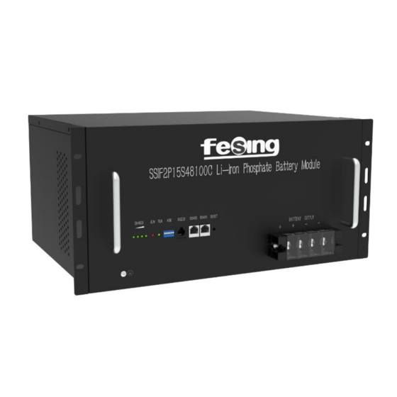
- Page 1 Application Manual LITHIUM BATTERY...
- Page 2 Read and follow these instructions! The following precautions are intended to ensure your safety and prevent property damage. Before installing this product, be sure to read all safety instructions in this document for proper installation. Failure to comply with the instructions with this symbol may result in a serious accident, causing death or a severe injury.
-
Page 3: Table Of Contents
Table of Contents Precautions ..........................4 1.1 General Safety Precautions ...................... 4 1.2 Installation Precautions ......................4 Product Introduction ........................5 2.1. Front Panel Function Introduction .................... 5 2.2 Product Specifications ......................6 2.3 State Indicator .......................... 8 Unpack the Battery ........................8 3.1 Parts List........................... -
Page 4: Precautions
1. Precautions 1.1 General Safety Precautions The product provides a safe source of electrical energy when operated as intended and as designed. Potentially hazardous circumstances such as excessive heat or electrolyte mist may occur under improper operating conditions, damage, misuse and/or abuse. The following safety precautions and the warning messages described in this part must be observed. -
Page 5: Product Introduction
Do not put tools or any metal parts on the top of the batteries. Disconnect charging source and load before connecting or disconnecting terminals. When moving batteries and wear all appropriate safety clothing and equipment. Do not open or mutilate the batteries. ▪... -
Page 6: Product Specifications
Figure 2-2: Front Panel Function Introduction 1. Reset: When the BMS is in the dormant state, press the button for 1S to activate the BMS. Meanwhile, the LED indicator will be lit to show SOC of the battery. When the BMS is in the active state, press the button for 3S to cause battery dormant. - Page 7 Basic Parameters Model SSIF2P15S48100C Anode Material LiFePO4 Nominal Voltage(V) Layout 15S1P 100(0.5C,25℃) Rated Capacity(Ah) Rated Energy(kWh) Dimensions(W×D×H)mm 440×350×222(5U) Weight(kg) 43.5(About) Communication RS485,CAN 6000+(80%DOD,25℃) Cycle Life Electrical Characteristics Voltage Window(V) 40.5~54 Charge Current(A) 50(Recommend) Max Charge Current(A) Max Discharge Current(A) Operation Environment 0℃~50℃...
-
Page 8: State Indicator
2.3 State Indicator Table 2-2: State Indicator Capacity LED System Mode Abnormal event De-energized/ No light No light All no light shutdown Mode Normal Flash 1 No light Indicate the SOC Stand-by Mode Alarm Flash 1 Flash 2 Indicate the SOC... -
Page 9: Parts List
according to the parts list. Violent unpacking is strictly prohibited. If the battery system is found to be broken, deformed or other abnormal conditions, the user shall immediately stop using the battery and contact us. 3.1 Parts List Check the parts during unpacking. Table 3-1: Parts Lists Items Appearance... -
Page 10: Visual Inspection Of The Modules
Fix the battery on the Cabinet bolt rack or cabinet Table 3-2: Recommended Tools and Instruments Items Usage Appearance To fasten battery and Phillips Screwdriver or Bit assemblies Box Cutter Opening boxes Insulated Torque Wrench Installing cables and busbars Insulated Sockets Installing cables and busbars Measure battery module’s Battery Tester... - Page 11 ▪ Be sure to use insulated tools (torque wrench, extension, socket, etc.). ▪ All the instruments must be insulated and no metal articles (e.g. watch, ring) should be present in the installation area. ▪ All power switches must be turned off in advance. ▪...
-
Page 12: Battery Module Installation
4.1 Battery Module Installation 1. Smoking and sparks are prohibited near batteries. 2. Use installation tools with insulated handles. Otherwise, the batteries may burn out and injury may be caused. 3. Before handling batteries, wear goggles, rubber gloves, and protective clothes. -
Page 13: Cable Connection
Figure 4-1: Battery Module Installation (A possible battery install procedure) 1. Please confirm the rack tray load bearing before installation. 2. Please make sure the rack depth meets the requirements before installation. 3. Support for 19" mounting, there should be rails and pallets, and make sure the load bearing meets the requirements. - Page 14 ▪ Before connect the cable with the inverter, the worker must confirm the output switch of the inverter has been turn off, to prevent the risk of fire or electric shock. ▪ Before connection, make sure to close the battery. ▪...
- Page 15 The power terminals, such as “+,” “-,” of the module are covered with the ▪ protecting cover to guard against a short circuit (Shown in Figure 5-1). ▪ You must remove the insulation cover prior to connecting and reattach the insulation cover immediately after connecting. Figure 5-1: Install the Grounding Wire Step 1 Wear the protective gloves.
- Page 16 Figure 5-2: Installing Negative and Positive Power Cables 1. Remove the protecting cover. 2. Take-down positive fixing bolt by the Phillips Screwdriver and connect the positive output cable between the battery positive terminal of the battery and the inverter. After connecting the battery, fastening bolt immediately to avoid dropping.
-
Page 17: Connect Cables Of The Multiple Batteries In Parallel
As shown in Figure 5-4, when monitoring the battery by the computer, connect the ‘USB convert to RS485’ communication line between battery and computer. Figure 5-4: Communication Cable Connections between Battery and Computer 5.2 Connect Cables of the Multiple Batteries in Parallel When multiple batteries in parallel, the cable connecting procedures are follows. - Page 18 2. As shown in Figure 5-7, connect the communication line (a standard RJ45 network cable) between the adjacent batteries. 3. When performing multi-machine parallel communication operation, it need to configure the dialing address of each battery. The dialing code is in BCD format, and the address 0 is defined as .
- Page 19 (a) RJ45 Pin Male (b) RJ45 Pin Female Figure 5-6: Communication Port Table 5-2: Description of RJ45 Pin RJ45 Pin Signal Meaning Description 2-wire RS485 communication, RS485 B complying with the Modbus protocol 2-wire RS485 communication, RS485 A complying with the Modbus protocol Reserved 2-wire CAN communication, CAN H...
-
Page 20: Visual Inspection Of The Connection
Figure 5-7: Communication Cable Connections among Multiple Batteries 5.3 Visual Inspection of the Connection After connecting the battery, check for: Usage of positive and negative cables. Connection of the positive and negative terminals. All the bolts are tightened. ... - Page 21 voltage were measured and viewed by the PC. When the current or BMS hardware problems occur, it will be displayed in a color corresponding state. (2) Prerequisites Windows 7 or later; Microsoft .NET Framework 4.0 or later. A USB-to-RS485 communications cable and a PC are available. You have obtained the Battery Station monitoring software.
-
Page 22: Inspection, Cleaning And Maintenance
Figure 6-2: System Monitoring Program 7. Inspection, Cleaning and Maintenance ▪ In case of maintenance or emergency, disconnect the DC circuit breaker on the battery side. ▪ Press and hold the battery reset key for 3S to turn off the battery. ▪... -
Page 23: Inspection
battery; After the battery product is over-discharged, it is recommended to charge the battery within 48 hours. The battery product can also be charged in parallel. After the battery product is connected in parallel, the charger only needs to connect the output port of any product battery. ... -
Page 24: Troubleshooting
than 48V, it must to be charged according to the charging strategy. The charging strategy is as follows: discharge the battery to the cutoff voltage with 0.2C current, and then charge with 0.2C A current for about 3 hours. Keep the SOC of the battery at 40-70% when stored;... -
Page 25: Battery Recovery
than 3.75 V in protection against 2. Cells are not consistent. The charging state. capacity of some cells deteriorates abnormality contact The battery too fast or the internal resistance local engineers rectify the fault. voltage is greater of some cells is too high. than 54 V. -
Page 26: Transportation Requirements
sulfuric acid solution and precipitated to obtain Al (OH) . When the pH value is above 9.0, most of the aluminum precipitates, and the obtained Al (OH) can reach the level of chemical purity after analysis. The filter residue is dissolved with sulfuric acid and hydrogen peroxide, so that lithium iron phosphate enters the solution in the form of Fe and Li , and is separated from carbon black and... - Page 27 lithium ion batteries which are assigned Class 9. Refer to relevant transportation documents. Lithium batteries and lithium ion cells are regulated in the U.S. in accordance with Part 49 of the Code of Federal Regulations, (49 CFR Sections 105-180) of the U.S. Hazardous Materials Regulations. Visit www.iata.org for the complete transport regulations and packing instructions for this product.
- Page 28 www.fns-power.com...
- Page 29 Battery compatibility statement The battery modules SSIF2P15S48100C produced by FnS Power Technology Inc. supply are compatible with the following inverters,: Invertter Manufacturer:FnS Power Technology Inc Model number: 1.Model:FR-7.6LM-EU 2.Model:FR-8LM-EU 3.Model:FR-6LM-EU 4.Model:FR-5LM-EU 5.Model:FR-3.6LM-EU Company:FnS Power Technology Inc. Signature: Job title:Chief engineer...
- Page 30 Version number V1.0 Document number QC-MS-002 Commencement date 2021.03.25 Lithium-ion Battery Module 10 Years Warranty Letter Edited by: ___________________ Reviewed by: ___________________ Approved by: ___________________ FnS Power Technology Inc.
- Page 31 CONTENTS 1. Limited Warranty Coverage......................3 2. Performance Warranty (Standard) ....................3 3. Limitation of Warranty Scope ......................4 4. Warranty Obligations ........................4 5. Exclusion of Warranty ........................5 6. Warranty Claims ..........................7 7. Important Notices ..........................7 8.Importer Information ........................
-
Page 32: Limited Warranty Coverage
(a) The ambient temperature during the operation of the Products shall not fall below 0℃ or exceed 50℃,and altitude not exceeding 3000m. (b) Recommended charging and discharging parameters Battery Module SSIF2P15S48100C High Battery Cut Off Voltage 52.5V Low Battery Cut Off Voltage 47.8V... -
Page 33: Limitation Of Warranty Scope
3. Limitation of Warranty Scope This Limited Warranty applies only to FnS Product: (a) Installed in covered locations including (Australia); (b) Purchased from FnS Power or authorized distributors,dealer or reseller; (c) Installed by a licensed professional or authorized installer; (d) The warranty date is calculated from the factory date of FnS Power; (e) Within the limited warranty period;... -
Page 34: Exclusion Of Warranty
may offer, at its option, to replace the Product with a new Product of similar function and performance or to credit the remaining depreciated value of the Product to be applied to purchase of new Product. The remaining depreciated value of the Product is determined by below and the price of the Product at the time that the Product was purchased. - Page 35 (b) Installation or commissioning by any person who is not an authorized, certified dealer or authorized, certified installer; (c) Negligent, reckless, or willful conduct on the part of an owner, authorized, certified dealer or authorized, certified installer, or any other third party; (d) Failure to observe the user manual, maintenance regulations and intervals;...
-
Page 36: Warranty Claims
(5) In no event will FnS Power be held responsible or liable for any personal injuries arising out of or connected with the use or misuse of the Covered Product, or for any other damages, whether direct, indirect, punitive, incidental, or consequential; even if FnS Power has been advised of such damages. - Page 37 overcharge, over-discharge and excessive load amperage, the FnS Power Lithium Batteries must always be installed with a charge controller and the appropriate settings to protect the FnS Power from open PV voltage and other high voltage charging sources. The FnS Power Lithium Battery Management System (BMS) alone will not protect the FnS Power Lithium batteries from these extreme electrical phenomena.
-
Page 38: Importer Information
repaired or replaced if the goods fail to be of acceptable quality and the failure does not amount to a major failure. 8.Importer Information Importer company name: YHI POWER PTY LTD Address: 20-22 Venture Way Braeside VIC 3195 Contact Number: 03 9588 1888 M 0413 381 228 Email: dchen@yhipower.com.au Website:... - Page 40 BL-DG2140965-302 1. Chemical Product and Company Identification Product Identification Product model: Li-ion Battery Nominal Voltage: 48V Capacity: 100Ah Weight: Approx. 46kg Physical Dimension: Approx. 440(Width)*350(Depth)*222(Height), unit: mm Manufacturer Shandong Sacred Sun Power Sources Co., Ltd. No 1, Shengyang Road, Qufu, Shandong Import agent Company name: YHI Power Pty Ltd Address: 20-22 Venture Way, Braeside VIC 3195, Australia...
- Page 41 BL-DG2140965-302 2. Hazards Identification Hazard class and label elements of the product according to GHS (the seventh revised edition): This product meets the definition of an article. Under the Globally GHS Hazard Class Harmonized System of Classification and Labeling of Chemicals (GHS), Articles as defined in the Hazard Communication Standard (29 CFR 1910.1200) of the Occupational Safety and Health Adm inistration of the United States of America, or by similar definition, are outside the...
- Page 42 BL-DG2140965-302 Emergency Overview May explode in a fire, which could release hydrogen fluoride gas. Use extinguishing media suitable for materials burning in fire. Primary routes of entry Skin contact : NO Skin absorption : NO Eye contact : NO Inhalation : NO Ingestion : NO...
- Page 43 BL-DG2140965-302 3. Composition Information Chemical Composition CAS Number Phosphate acid, iron(2+), lithium 25-30 15365-14-7 salt(1:1:1) Graphite 8-12 7782-42-5 Phosphate(1-), hexafluoro-, lithium 15-22 21324-40-3 Aluminum 7429-90-5 Copper 10-15 7440-50-8 High molecular polymer Nickel 0.5-1 7440-02-0 Iron 22-30 7439-89-6 5 / 18...
- Page 44 BL-DG2140965-302 4. First Aid Measures Description of First Aid Measures Immediate medical attention is required. Show this General Advice safety data sheet (SDS) to the doctor in attendance. Rinse thoroughly with plenty of water for at least Eye Contact 15 minutes and consult a physician if feel uncomfortable.
- Page 45 BL-DG2140965-302 5. Fire Fighting Measures General Hazard Cell is not flammable. Combustion products include, but are not limited to Hydrogen fluoride, carbon monoxide and carbon dioxide. Extinguishing Media Water dry chemical, carbon dioxide or alcohol resistant foam. Specific Hazards Arising from the Substance or Mixture 1.
- Page 46 BL-DG2140965-302 6. Accidental Release Measures Personal Precautions, Protective Equipment and Emergency Procedures 1. Ensure adequate ventilation. Remove all sources of ignition. 2. Evacuate personnel to safe areas. Keep people away from and upwind of spill/leak. 3. Use personal protective equipment. Avoid breathing vapours, mist, gas or dust. Environmental Precautions 1.
- Page 47 BL-DG2140965-302 8. Exposure Controls/Personal Protection Control Parameters Occupational Exposure Limit Values Biological Limit Values No information available Monitoring Methods 1. EN 14042 Workplace atmospheres. Guide for the application and use of procedures for the assessment of exposure to chemical and biological agents. 2.
- Page 48 BL-DG2140965-302 9. Physical and Chemical Properties Appearance: Lithium ion batteries, individually Odor Threshold: No information available Melting Point/Freezing Point (℃): No information available Flash Point (℃)( Closed Cup): Not applicable Flammability: No information available Vapor Pressure (MPa): Not applicable Relative Density(Water=1): No information available N Octanol/Water Partition Coefficient: No information available...
- Page 49 BL-DG2140965-302 10. Stability and Reactivity Reactivity Contact with incompatible substances can cause decomposition or other chemical reactions. Chemical Stability Stable under proper operation and storage conditions. Possibility of Hazardous Reactions Ultrafine powder will self ignite in the air at room temperature. Reacts severely with halogens, interhalogens or other strong oxidants, or causes a fire.
- Page 50 BL-DG2140965-302 11. Toxicological Information Acute Toxicity No information available Serious Eye Damage/Irritation No information available Skin Sensitization No information available Respiratory Sensitization No information available Germ Cell Mutagenicity No information available Carcinogenicity CAS No. Component IARC Phosphate acid, iron(2+), lithium 15365-14-7 Not Listed Not Listed...
- Page 51 BL-DG2140965-302 Reproductive Toxicity (Additional) No information available STOT Single Exposure No information available STOT Repeated Exposure No information available Aspiration Hazard No information available 13 / 18...
- Page 52 BL-DG2140965-302 12. Ecological Information Acute Aquatic Toxicity Chronic Aquatic Toxicity No information available Others Persistence and No information available Degradability Bioaccumulative No information available Potential Mobility in Soil No information available Results of PBT and vPvB Aluminium foil does not meet the criteria for PBT and vPvB according Assessment to Regulation (EC) No 1907/2006, annex XIII.
- Page 53 BL-DG2140965-302 13. Disposal Considerations Waste Chemicals Before disposal should refer to the relevant national and local laws and regulation. Recommend the use of incineration disposal. Contaminated Packaging Containers may still present chemical hazard when empty. Keep away from hot and ignition source of fire.
- Page 54 BL-DG2140965-302 14. Transport Information In the case of transportation, confirm no leakage and no overspill from a container. Take in a cargo of them without falling, dropping and breakage. Prevent collapse of cargo piles and wet by rain. The container must be handled carefully. Do not give shocks that result in a mark of hitting on a pack.
- Page 55 BL-DG2140965-302 15. Regulatory Information OSHA Hazard communication standard (29 CFR 1910.1200) __________Hazardous √ Non-hazardous Component EINECS TSCA IECSC NZIoC PICCS KECI AICS ENCS Aluminium √ √ √ √ √ √ √ √ × Copper √ √ √ √ √ √ √...
Need help?
Do you have a question about the SSIF2P15S48100C and is the answer not in the manual?
Questions and answers