Table of Contents
Advertisement
Quick Links
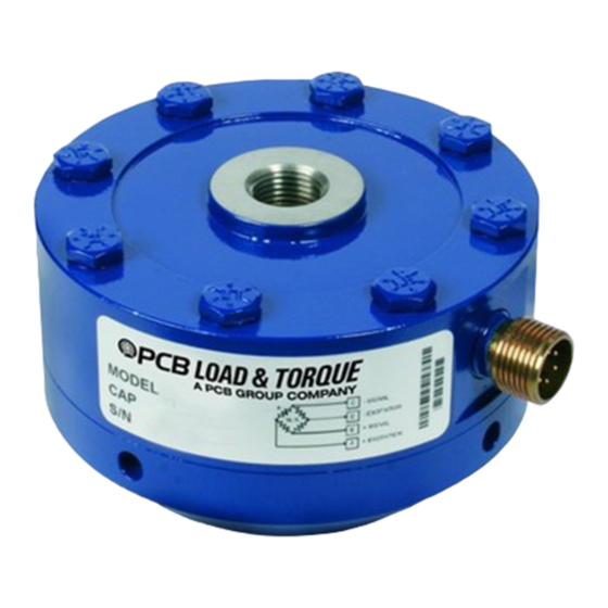
Model M1403-03ADB
FATIGUE RATED LOW PROFILE LOAD CELL, DUAL BRIDGE, METRIC
Installation and Operating Manual
For assistance with the operation of this product,
contact PCB Piezotronics, Inc.
Toll-free: 800-828-8840
24-hour SensorLine: 716-684-0001
Fax: 716-684-0987
E-mail: info@pcb.com
Web: www.pcb.com
Advertisement
Table of Contents

Related Manuals for PCB Piezotronics M1403-03ADB


Summary of Contents for PCB Piezotronics M1403-03ADB
- Page 1 Model M1403-03ADB FATIGUE RATED LOW PROFILE LOAD CELL, DUAL BRIDGE, METRIC Installation and Operating Manual For assistance with the operation of this product, contact PCB Piezotronics, Inc. Toll-free: 800-828-8840 24-hour SensorLine: 716-684-0001 Fax: 716-684-0987 E-mail: info@pcb.com Web: www.pcb.com...
- Page 2 Piezotronics, user servicing or repair is critical test. not recommended and, if attempted, may void the factory warranty. Routine PCB Piezotronics maintains an ISO- maintenance, such as the cleaning of 9001 certified metrology laboratory and electrical connectors, housings, and offers calibration services, which are...
- Page 3 50% of the general contact numbers are: replacement cost returned item(s). PCB will provide a price PCB Piezotronics, Inc. quotation replacement 3425 Walden Ave. recommendation for any item whose Depew, NY14043 USA repair costs would exceed 50% of...
- Page 4 PCB工业监视和测量设备 - 中国RoHS2公布表 PCB Industrial Monitoring and Measuring Equipment - China RoHS 2 Disclosure Table 有害物质 汞 镉 六价铬 (Cr(VI)) 多溴联苯 (PBB) 多溴二苯醚 (PBDE) 部件名称 铅 (Pb) (Hg) (Cd) 住房 PCB板 电气连接器 压电晶体 环氧 铁氟龙 电子 厚膜基板 电线 电缆 塑料 焊接...
- Page 5 Component Name Hazardous Substances Lead Mercury Cadmium Chromium VI Polybrominated Polybrominated (Pb) (Hg) (Cd) Compounds Biphenyls Diphenyl (Cr(VI)) (PBB) Ethers (PBDE) Housing PCB Board Electrical Connectors Piezoelectric Crystals Epoxy Teflon Electronics Thick Film Substrate Wires Cables Plastic Solder Copper Alloy/Brass This table is prepared in accordance with the provisions of SJ/T 11364.
-
Page 6: Table Of Contents
DUAL BRIDGE LOAD CELL OPERATION MANUAL TABLE OF CONTENTS 1.0 INTRODUCTION........................2 2.0 SAFETY PRECAUTIONS ....................2 3.0 OVERVIEW .......................... 2 3.1 Dimensions ............................2 3.2 Standard Components ........................3 3.3 Optional Components ........................3 4.0 MECHANICAL INSTALLATION ..................3 4.1 Mounting Bases ..........................3 4.2 Mounting Load Cell to a Standard Base or Custom Fixture .............3 4.3 Threaded Tension Rods........................4 4.4 Mounting Optional Connector Protectors..................4... -
Page 7: Introduction
DUAL BRIDGE LOAD CELL OPERATION MANUAL 3.1 Dimensions 1.0 INTRODUCTION The following figure and table give the general outline Dual bridge fatigue-rated load cells manufactured by PCB dimensions of the dual bridge fatigue-rated load cells. Load and Torque, Inc. are guaranteed to last 100 million fully reversed cycles (full tension through full compression). -
Page 8: Standard Components
DUAL BRIDGE LOAD CELL OPERATION MANUAL 3.2 Standard Components 4.0 MECHANICAL INSTALLATION The following figure describes the standard components of the Standard components of the dual bridge fatigue-rated load dual bridge fatigue-rated load cells. cells have all been installed to factory specified values for optimum performance. -
Page 9: Threaded Tension Rods
DUAL BRIDGE LOAD CELL OPERATION MANUAL Table 4 – Tension Base Installation Torque Values Bolt Size Part Number Installation Torque 1/4-28x1 3/4 100-8011-10 15-17 LbFt (180-204 LbIn) 100-8082-20 75-80 LbFt (900-960 LbIn) 3/8-24x2 1/4 100-8011-30 120-130 LbFt (1440-1560 LbIn) 1/2-20x3 1/2 3/4-16x4 1/2 100-10026-40 370-400 LbFt (4440-4800 LbIn) -
Page 10: Electrical Installation
DUAL BRIDGE LOAD CELL OPERATION MANUAL 5.2 Cable & Grounding Considerations Proper grounding and shielding is required to prevent electrical noise in strain gage load cell measuring systems. The cable must be shielded twisted pairs with a drain wire. Cable shields must be grounded only at one end, for example, on the instrument or control system ground. -
Page 11: Measured Output
DUAL BRIDGE LOAD CELL OPERATION MANUAL 6.1.1 Measured Output 7.0 MOMENT COMPENSATION The applied load starting at zero is measured in five When an eccentric axial load is Primary increments to full scale. Output (mV/V) is measured at each applied to a load cell that is not Axis increment. -
Page 12: Shunt Calibration Description
DUAL BRIDGE LOAD CELL OPERATION MANUAL 9.1 Resistor Value Aircraft Quality Steel Alloy Dual bridge load cells have a nominal 2.0 mV/V full scale Steel Safety Factor > 2.5 Aluminum Alloy output. For a 350 ohm strain gage bridge the precision shunt Aluminum Safety Factor ≈... -
Page 13: Trouble Shooting
DUAL BRIDGE LOAD CELL OPERATION MANUAL Dual bridge fatigue rated load cells, when mounted on the 11.2.1 Estimating Bridge Balance using an Ohm Meter factory supplied base, are barometric compensated through a small port located in one of the spanner wrench holes on the A load cell that has been severely overloaded will exhibit a base. -
Page 14: Rma / Purchase Order
DUAL BRIDGE LOAD CELL OPERATION MANUAL Certificate information includes tabulated measurement variable data zero balance, bridge input/output resistance, computer nonlinearity and hysteresis, static error band (SEB) calculations and entries abilities and traceability statements. If an initial evaluation shows that a transducer requires repair, PCB will provide the customer with an estimate prior to taking any corrective action. - Page 15 Model Number Revision: NR FATIGUE RATED LOW PROFILE LOAD CELL, DUAL BRIDGE, METRIC M1403-03ADB ECN #: 43174 Performance ENGLISH OPTIONAL VERSIONS Measurement Range(100 x 10^6 cycles) 1011 lbf 4500 N [5][6] Optional versions have identical specifications and accessories as listed for the standard Sensitivity(±...
- Page 16 PCB Load & Torque Inc. claims proprietary rights in REVISIONS the information disclosed hereon. Neither it nor any reproduction thereof will be disclosed to others without DESCRIPTION the written consent of PCB Load and Torque Inc. CONNECTOR "B" HUB DIAMETER WAS 1.25 [31.8] - 10.05.16, PTE 46027 22.5°...
Need help?
Do you have a question about the M1403-03ADB and is the answer not in the manual?
Questions and answers