
Related Manuals for DX Patrol QO-100

Summary of Contents for DX Patrol QO-100
- Page 1 QO-100 DX Patrol Ground Station An all-in-a-box station for easy QO-100 operation DX PATROL August 12, 2021 Authored by: CT1FFU v2.0...
- Page 2 QO-100 DX Patrol Ground Station An all-in-a-box station for easy QO-100 operation An all-in-a-box station for easy QO-100 operation...
-
Page 3: Table Of Contents
DX P LNB .................... 17 ODIFIED ATROL DX P GPS + G ................17 ATROL LONASS ANTENNA ....................18 VAILABLE ACCESSORIES DX PATROL H QO-100 ................18 ELIX ANTENNA DXPATROL ................... 19 STANDALONE .................... 20 OAX CABLE CONSIDERATIONS ....................20... -
Page 4: Main Characteristics
Main Characteristics. The Ground Station works as a simplex radio station (RX/TX on 70cm) It’s up to the operator, to arrange continuous monitoring of his signal via WEBSDR or other means like separate RX convertor *, as recommended by AMSAT. •... -
Page 5: Simplified Block Diagram
Simplified block Diagram... -
Page 6: General Overview
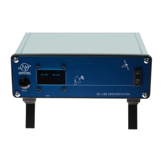
General overview Front view The Ground Station has 2 tilt feet on the bottom, front side, for easy access and use. Left the menu button, next OLED screen and on the right the ON/OFF switch. Rear view... -
Page 7: Connecting The Ground Station
Connecting the Ground Station Equipment needed. A power supply 12V or ( 13,8V) 5A minimum; Two coaxial TV 75 Ohm cables for satellite LNB fitted with male F connectors; Low loss coax cable (50ohm) from RF out to patch/helix antenna. How t o connect? WARNING Never make these connections with Ground Station ON. -
Page 8: Operating The Ground Station
Swi tch the Ground Station on with the switch on the frontpanel. When turning ON you will see for some seconds the Splash Screen Logo of DX patrol and then the display will present a page as show in the picture below. -
Page 9: Satellite Input Power
Satellite input power This page shows input satellite strength. This is shown in dBm and it's very useful to point the dish and fine adjustment of LNB in the focal point. Information menu This page shows: the input DC voltage; ... -
Page 10: Gps Menu
GPS menu Overview of the GPS data. Geographic Coordinates; Date and UTC time; Number of GPS in range; WW QTH locator. Ground Station informati on Current FW version (August 2021) Serial number. -
Page 11: Ready For Operation
433.000 MHz. The Ground Station will receive the QO-100 very clearly with the included LNB with any dish, even small ones as 30 cm. However, in transmission, to have a clear loud signal, you should use a minimum 60cm dish and an efficient antenna feed, such as a Helix or a Patch antenna, low loss cable as short as possible is preferred to feed the 2.4 GHz... -
Page 12: Current Bandplan
Cur rent band plan NB transponder Bandplan Mode Down 432,500 2400,000 CW beacon 10489,500 432,505 2400,005 10489,505 CW only 432,540 2400,040 10489,540 NB digital modes 432,580 2400,080 10489,580 Digital modes 432,650 2400,150 10489,650 SSB only 432,745 2400,245 10489,745 PSK beacon 432,255 2400,255 10489,755... -
Page 13: Adjustments
Adjustments IF Levels The set input level (factory setting) is 250mW. For maximum versatility the required input power of the Ground Station can be adjusted on the inside. The RX gain can be adjusted as well. P38 sets the TX gain level. R13 sets the RX gain level. -
Page 14: Power Meter Level
Power meter level These are factory set and should not be adjusted without the proper external power meter equipment. R59 sets the forward power level indicated on the OLED display. R61 sets the SWR level indicated on the OLED display. -
Page 15: Detailed Views And Schematic
Detailed views and schematic Inside vi ews Power amplifier on the bottom of the case... - Page 16 On the left the 12v->28volts convertor, on the right the top board holding the RF parts GPS module Transverter output to final power amplifier...
-
Page 17: Ptt/Vox Circuit
PTT connection, like a simple RCA jack, on the back of the QO-100 Ground station. The F6 connection can be used to bypass the PA PTT as well, this is useful if you use very drive levels to the QO-100... -
Page 18: Included Parts List
Included parts list Modified DX Patr ol LNB DX P atrol GPS + Glonass antenna... -
Page 19: Available Accessories
Available accessories DX P ATROL Helix QO-100 antenna With quick mount system... -
Page 20: Dxpatrol Standalone Rx Set
DXPATROL standalone RX set... -
Page 21: Coax Cable Considerations
Coax cable considerations Make no mistake, coaxial cable loss at 2.4 GHz can be high, so it’s important to use good quality coaxial cable form the feed to the Ground Station. Following table gives You an idea about the expected losses @2.4GHz just for 1 meter of coaxial cable! Loss Diameter...
Need help?
Do you have a question about the QO-100 and is the answer not in the manual?
Questions and answers