Table of Contents
Advertisement
Quick Links
Advertisement
Table of Contents

Summary of Contents for Deeter Electronics LVCSi
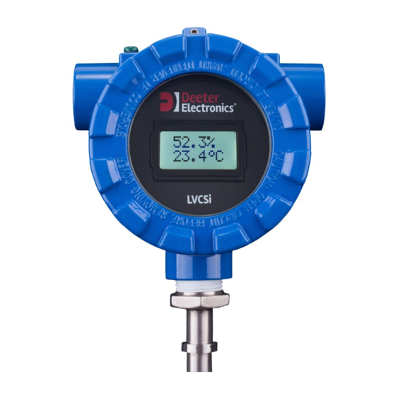
- Page 1 LVCSi Continuous Vertical Level Sensor with Integrated Display Page 1 of 32...
-
Page 2: Table Of Contents
LVCSi Continuous Vertical Level Sensor with Integrated Display Table of Contents Introduction ........................3 Main Features ........................4 Sensor Inputs ............................ 4 Display ............................... 5 Analogue Outputs ..........................6 Digital Outputs..........................7 Serial Communications ........................7 Installation .......................... 8 Mounting the Sensor Stem ......................8 External Wiring .......................... -
Page 3: Introduction
LVCSi Continuous Vertical Level Sensor with Integrated Display 1. Introduction The LVCSi is an analogue vertical level sensor with an integrated display meter and output driver specifically designed for continuous, in-situ monitoring of your tank. It is an extension of Deeter Electronics’... -
Page 4: Main Features
Figure 1 – a typical response for an LVCSi at ambient temperature plunged into water at 90°C, compared with a steel reference thermometer probe, 3.2mm in diameter. -
Page 5: Display
LVCSi Continuous Vertical Level Sensor with Integrated Display Display The display is a 2-line by 8-character backlit LCD. In normal operation the top line shows level information and the bottom line shows temperature. If a temperature sensor is not fitted, the bottom line remains blank. -
Page 6: Analogue Outputs
LVCSi Continuous Vertical Level Sensor with Integrated Display Analogue Outputs Analogue Output 1 is assigned to the level input only. If a temperature sensor is fitted, Analogue Output 2 can be assigned to level or temperature. Each output has four ranges: 4-20mA, 0-10V, 0-5V and 0-2V. (If a temperature sensor is not fitted Analogue Output 2 is limited to the three voltage options.) -
Page 7: Digital Outputs
8 data bits, no parity and 1 stop bit. There are four user-selectable baud rates: 2400, 9600, 19200 and 38400. The LVCSi is a slave device, responding to commands initiated by a bus master. A simplified ASCII protocol, ‘Deeter ASCII’, comes as standard. This uses ASCII characters in the displayable range 20h to 7Eh, making commands easy to generate and responses easy to view and interpret on a PC with readily available terminal-emulation software. -
Page 8: Installation
LVCSi Continuous Vertical Level Sensor with Integrated Display 3. Installation Mounting the Sensor Stem To mount the LVCSi in a tank, first separate the two assemblies: unscrew and remove the glass cover of the head assembly pull off the LCD surround ... -
Page 9: Analogue Outputs
LVCSi Continuous Vertical Level Sensor with Integrated Display 3.2.2 Analogue Outputs There are two independently driven analogue outputs, each having terminals for voltage and current, making four analogue outputs in total. These are arranged as a single block of 8 screw terminals on the underside of the bottom PCB. -
Page 10: Rs485 Communications
TERM position. Inverting the LVCSi The LVCSi can be mounted to the top or bottom of a tank. Default settings are for top-mounting, with low analogue and display levels associated with the float at the end of the stem away from the head. -
Page 11: Configuration Setup
LVCSi Continuous Vertical Level Sensor with Integrated Display 4. Configuration Setup Three push buttons are used to navigate the configuration menus. These buttons are located below the display and are only accessible with the housing cover unscrewed, so configuration setup needs to be performed during installation. If Modbus communications options are used, most setup parameters (excluding communications settings) can be changed remotely at any time. - Page 12 LVCSi Continuous Vertical Level Sensor with Integrated Display Page 12 of 32...
-
Page 13: Level Display
LVCSi Continuous Vertical Level Sensor with Integrated Display Level Display During normal operation the top line of the display is reserved for level information. The first sub-menu selects the location of the decimal place. The five options are: The ‘x10’ option multiplies all numbers by ten without increasing resolution, so the last digit is shown as zero. -
Page 14: Temperature Display
LVCSi Continuous Vertical Level Sensor with Integrated Display The fourth and final sub-menu selects display units: < > Unit options are listed in Table 1. Temperature Display Temperature can be displayed in degrees Celsius, degrees Fahrenheit or in Kelvin °... -
Page 15: Analogue Output 1
LVCSi Continuous Vertical Level Sensor with Integrated Display Analogue Output 1 Analogue Output 1 is always associated with the level input. The first sub-menu is used to select output range. UP and DOWN cycle through the 4 options. The 4-20mA and 0-10V options produce the same outputs. They differ in that the 4-20mA option will raise an alarm if the current loop is broken, or if the loop resistance is too great or supply voltage is too low for the driver IC to achieve the correct output current. -
Page 16: Analogue Output 2
LVCSi Continuous Vertical Level Sensor with Integrated Display Analogue Output 2 For an LVCS stem with a temperature sensor, Analogue Output 2 can be assigned to level or temperature and the first sub-menu is used to make that selection: Whichever input is chosen, the second sub-menu selects output range: With a temperature sensor fitted the four options are: 4-20mA, 0-10V, 0-5V and 0-2V. -
Page 17: Analogue Output Calibration
For the 50°C range the zero can be between –40°C and +70°C Analogue Output Calibration The LVCSi is calibrated during manufacture and under normal circumstances further adjustments should not be necessary. In order to perform calibration adjustments effectively, set Analogue Output 2 to LEVEL and both output channels to a full range, either 4-20mA or 0-10V (see section 4.6). - Page 18 LVCSi Continuous Vertical Level Sensor with Integrated Display The three top left characters indicate current (C) or voltage (V), channel number (1 or 2) and Zero (Z) or Span (S). There are separate calibration settings for the current-loop and voltage outputs for each output channel, making four sets of calibration settings in total.
-
Page 19: Temperature Sensor Calibration
LVCSi Continuous Vertical Level Sensor with Integrated Display Temperature Sensor Calibration This menu is only seen if a temperature sensor is fitted. Calibration is performed during manufacture at an indoor ambient temperature and further adjustments should not be necessary. The adjustment is a fixed offset applied across the full temperature range and accuracy will be greatest close to the temperature at which calibration is performed. -
Page 20: Digital Output Test
LVCSi Continuous Vertical Level Sensor with Integrated Display If TEMP is chosen, thresholds are shown as a temperature in degrees Celsius (integers only) ° ° ENTER advances to Transistor 2 settings. Options for Transistor 2 are equivalent to those shown above for Transistor 1. -
Page 21: Operating States
In the normal state the backlight will dim to the level selected in setup. Start-up The display shows the firmware version for 5 seconds when the LVCSi is switched on, then advances to normal operation or fault states. Normal Operation During normal operation the top line of the display will show level information and the bottom line will show the temperature. -
Page 22: Missing Level Sensor
This may indicate a fault in the stem, but is normal for some types of LVCS. Missing Temperature Sensor If the LVCSi is configured for a temperature sensor and this is disconnected, the bottom line will show ‘NO INPUT’. Outputs associated with temperature will go to 0mA and 0V. -
Page 23: Rs485 Serial Communications
LVCSi Continuous Vertical Level Sensor with Integrated Display 6. RS485 Serial Communications The LVCSi is a slave device responding to commands initiated by an RS485 bus master. The data format is fixed as: 8 data bits, no parity, 1 stop bit. - Page 24 LVCSi Continuous Vertical Level Sensor with Integrated Display Analogue Output Settings contains 11 comma-separated numbers: An1 settings An1current zero, An1current span, An1 voltage zero, An1voltage span An2 settings An2 current zero, An2 current span, An2 voltage zero, An2 voltage span...
- Page 25 LVCSi Continuous Vertical Level Sensor with Integrated Display The level-decimal-places-and-units number is hexadecimal with the following bit assignments: Table 5 Bits Function Bit Settings Not used, always 00 100 = x10 011 = 3 6,5,4 Number of decimal places 010 = 2...
- Page 26 LVCSi Continuous Vertical Level Sensor with Integrated Display Level reports show the current float level in decimal between 0000 and 1000 The firmware version is the same as that displayed on power-up. Up to three comma-separated characters follow the version number: ‘2’, ‘3’...
-
Page 27: Modbus Rtu
Modbus RTU is a de facto standard, having achieved wide acceptance for connecting industrial devices without rigid standardisation or formal acceptance by standards authorities. The LVCSi conforms to the Modbus RTU command and response framing standard as a slave device. Detailed descriptions of this standard are readily available on the world-wide web. -
Page 28: Bit Assignments
LVCSi Continuous Vertical Level Sensor with Integrated Display There are eleven read-only registers, accessed by function code 4, defined as follows: Table 8 Register Address Description Comments 30001 0000 Firmware version e.g. V1.02 will be sent as 0102 30002 0001... - Page 29 LVCSi Continuous Vertical Level Sensor with Integrated Display Registers 40003 to 40006 contain the transistor ON and OFF thresholds. Level thresholds are between 0 and 100 percent; temperature thresholds are in degrees Celsius from –40°C to +120°C represented as numbers from 0 to 160.
-
Page 30: Broadcast And Exception Responses
LVCSi will also ignore this command and not respond. If the slave address is correct and there are no errors in the transmission, but the LVCSi cannot action the command for another reason, it will reply with an exception response. -
Page 31: Modbus Ascii
40010 will cause this response Modbus ASCII The LVCSi conforms to the Modbus ASCII command and response framing standard, details of which are readily available on the world-wide web. Supported function codes, register assignments, bit assignments and exception responses are the same as those described above for Modbus RTU. -
Page 32: Specifications
LVCSi Continuous Vertical Level Sensor with Integrated Display 7. Specifications Head dimensions: 110mm x 100mm x 81mm (Excluding sensor stem and cable glands/port fixings) Stem length: Standard sizes are from 0.25m to 2m in 0.25m increments. Custom sizes available on request...
Need help?
Do you have a question about the LVCSi and is the answer not in the manual?
Questions and answers