Table of Contents
Advertisement
Quick Links
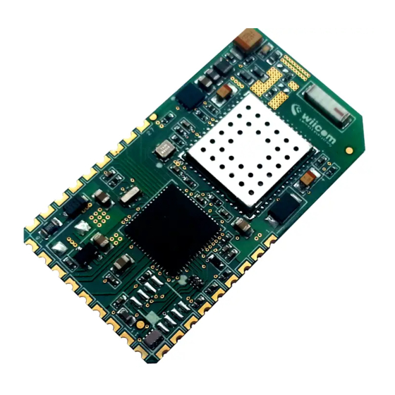
AC8401
Version:1.0
Module characteristics
Support IEEE 802.11a/b/g/n wireless
standard
Support WEP, WPA and WPA2 encryption
Support UART / PWM / ADC / GPIO / I2C
/ SPI interface
Support STA / AP and other working
modes
Support Amazon FFS distribution
network
Support TLS / SSL Protocol
Support PCB antenna
3.3V power supply
Peripheral equipment:
2x UART
1x I2C
1x SPI
5x PWM
4x ADC
Up to 14GPIOs
Embedded Wi Fi module
Release date: 2021 年 02 月 19 日
Working environment temperature: -
20 ℃ to + 85 ℃
Half hole SMT package supporting SMT
Application
Electrical lighting
smart home / home appliances
instrumentation
health care
Industrial automation
smart energy
MODEL
Model
AC8401
Antenna type explain
PCB Antenna
Default
Advertisement
Table of Contents

Summary of Contents for Asiacom Technology AC8401
- Page 1 AC8401 Embedded Wi Fi module Release date: 2021 年 02 月 19 日 Version:1.0 Module characteristics Working environment temperature: - Support IEEE 802.11a/b/g/n wireless 20 ℃ to + 85 ℃ standard Half hole SMT package supporting SMT ...
-
Page 2: Table Of Contents
3.2.1 IEEE802.11b Mode ....................- 5 - 3.2.2 IEEE802.11g Mode ....................- 6 - 3.2.3 IEEE802.11n Mode ....................- 7 - 4. AC8401 essential information ..................- 10 - 4.1 Pin arrangement ......................- 10 - 4.2 Pin definition ......................- 10 - 4.2.1 Module hardware pin definition ................ -
Page 3: Electrical Parameters
- 3 - Product introduction AC8401 is a high cost-effective embedded WiFi module introduced by Asean that supports 802.11a/b/g/n and can communicate with other devices via UART port.The module integrates RF transceiver, MAC, baseband processing, all WiFi protocols and configuration information, and network protocol stack. -
Page 4: Work Environment
- 4 - 2.2 work environment The working environment is detailed in Table 2 Table 2 AC8401 Work Environment Symbol Description Min. Max. Units ℃ Storage temperature ℃ Ambient operating temperature Supply voltage Voltage on IO pin 1000 2000 3. Radio Frequency Parameters 3.1 Basic Radio Frequency Parameters... -
Page 5: Tx、Rx Performance
- 5 - 3.2 TX、RX performance 3.2.1 IEEE802.11b Mode Table 4 3.2.1 basic parameters of IEEE802.11b mode ITEM Specification Modulation Type DSSS / CCK 2412MHz~2462MHz Frequency range Channel CH1 to CH11 Data rate 1, 2, 5.5, 11Mbps Table 4 transmitting performance parameters in IEEE802.11b mode TX Characteristics Typical Max. -
Page 6: Ieee802.11G Mode
- 6 - 3.2.2 IEEE802.11g Mode Table 6 basic parameters in IEEE802.11g mode ITEM Specification Modulation Type OFDM 2412MHz~2462MHz Frequency range CH1 to CH11 Channel 6, 9, 12, 18, 24, 36, 48, 54Mbps Data rate Table 7 transmitting performance parameters in IEEE802.11g mode TX Characteristics Typical Max. -
Page 7: Ieee802.11N Mode
- 7 - 3.2.3 IEEE802.11n Mode Table 9 basic parameters of ieee802.11n in 20MHz mode ITEM Specification Modulation Type OFDM 2412MHz~2462MHz Frequency range CH1 to CH11 Channel MCS0/1/2/3/4/5/6/7 Data rate Table 10 transmission performance parameters of ieee802.11n in 20MHz mode TX Characteristics Typical Max. - Page 8 - 8 - Table 14 transmission performance parameters in ieee802.11n 5g 20MHz mode TX Characteristics Typical Max. Unit 12.5 Power@HT20, MCS7 Frequency Error -30.5 EVM@HT20, MCS7 Transmit spectrum mask Pass Table 15 receiving performance parameters in ieee802.11n 5g 20MHz mode RX Characteristics Typical Max.
- Page 9 - 9 - Table 18 receiving performance parameters of ieee802.11n in 40MHz mode RX Characteristics Typical Max. Unit Minimum Input Level Sensitivity MCS7 Maximum Input Level (FER≦ 10%) Table 19 basic parameters of ieee802.11n 5g 40MHz mode ITEM Specification Modulation Type OFDM 5.15GHz-5.25GHz Frequency range...
-
Page 10: Ac8401 Essential Information
- 10 - 4. AC8401 essential information 4.1 Pin arrangement AC8401 pin arrangement is shown in Figure 1. 图 1 AC8401 引脚排列示意图 4.2 Pin definition 4.2.1 Module hardware pin definition Table 15 for the definition of module hardware pins Table 14 for AC8401 pin definition annotation... - Page 11 - 11 - GPIO04 Debug_UART_TX PWM4 GPIO05 UART1_RTS GPIO06 UART1_RXD Enable pin GPIO08 SPI_M_CLK GPIO09 UART1_CTS GPIO10 SPI_M_MISO GPIO12 SPI_M_MOSI GPIO13 SPI_M_CS GPIO07 UART1_TXD GPIO00 PWM0 GPIO20 GPIO21 I2C_SCL Debug_UART_RX GPIO22 I2C_SDA Debug_UART_TX Power VDD33 supply 3.3V Ground Note: 1. By default, uart1 (pin7, PIN14) is used for general transparent transmission, UART0 (pin4, pin5) is used for debug information output and firmware upgrade, and the serial port output level is described by DC characteristics.
-
Page 12: Built In Antenna
图 2 AC8401 Antenna diagram The gain of PCB antenna of this module is about 0dB, as shown in Figure 3. -
Page 13: Mechanical Dimension
PCB layout, as shown in the figure below, so as to ensure the good performance of the antenna. Figure 4 AC8401 Recommended PCB layout 4.4 Mechanical dimension The dimensions of AC8401 module are shown in Figure 5. -
Page 14: Recommended Package Size
Figure 5 AC8401 Module dimension drawing a. Description: dimension (15 ± 0.2) mm * (21 ± 0.2) mm * (2.6 ± 0.2) mm (with shield) 4.5 Recommended package size See Figure 6 for the recommended package dimensions of AC8401. 图 3 AC8401 recommended package dimensions... -
Page 15: Reference Design
- 15 - 5. Reference design 5.1 UARTinterface design For 3.3V power supply equipment, the serial port of equipment and module can be directly connected to complete communication according to the circuit shown in Figure 7. Table 4 Circuit diagram(3.3V) For 5V power supply equipment, refer to the circuit shown in Figure 8 or design relevant level conversion circuit. -
Page 16: Power Supply Requirements
- 16 - Table 5 Circuit diagram(5V) 5.2 Power supply requirements Power supply requirements: if 3.3V voltage is generated by LDO to supply power to the module, the capacitance value of C1 can be considered as 10uF ~ 22uF; if 3.3V voltage is generated by DCDC power supply to supply power to the module, the capacitance value of C1 can be considered as 22uF. -
Page 17: Certification Instructions
2AY4V-AC8401” or “Contains transmitter module FCC ID: 2AY4V-AC8401”. 2.9 Information on test modes and additional testing requirements Contact Asiacom Technology Ltd. will provide stand-alone modular transmitter test mode. Additional testing and certification may be necessary when multiple modules are used in a host. - Page 18 - 18 - ensuring compliance with the module(s) installed and fully operational. For example, if a host was previously authorized as an unintentional radiator under the Supplier’s Declaration of Conformity procedure without a transmitter certified module and a module is added, the host manufacturer is responsible for ensuring that the after the module is installed and operational the host continues to be compliant with the Part 15B unintentional radiator requirements.
- Page 19 - 19 - in the end-user operating manual of final products. Note 3: The module may be operated only with the antenna with which it is authorized. Any antenna that is of the same type and of equal or less directional gain as an antenna that is authorized with the intentional radiator may be marketed with, and used with, that intentional radiator.
Need help?
Do you have a question about the AC8401 and is the answer not in the manual?
Questions and answers