
Related Manuals for FMX TD400 Series


Summary of Contents for FMX TD400 Series
- Page 3 Table of Contents Chapter 1: Safety Precautions 1.1 Before supplying Power to the AC Drive 1.2 Wiring 1.3 Before Operation 1.4 Auto Tuning 1.5 Operation 1.6 Maintenance, Inspection, and Replacement 1.7 Disposal of the AC Drive 1.8 UL Standards Chapter 2: Model Description 2.1 Nameplate Data 2.2 Wire Gauge, Tightening Torque, Terminal, Short Circuit, Circuit Breaker, and Fuse Ratings 2.3 AC Drive Specifications...
- Page 4 Group 05 Preset Frequency Parameters 4-91 Group 06 Automatic Program Operation 4-95 Group 07 Start/Stop Parameters 4-99 Group 08 Protection Parameters 4-111 Group 09 Communication Parameters 4-120 Group 10 PID Parameters 4-121 Group 11 Auxiliary Parameters 4-130 Group 12 Monitoring Parameters 4-139 Group 13 Maintenance Parameters 4-142...
- Page 5 1. Safety Precautions 1.1 Before supplying Power to the AC Drive Warning: MAIN CIRCUIT POWER SUPPLY TERMINALS MUST BE CORRECTLY WIRED Single Phase Input: L1(L) and L3(N) Three Phase Input: L1(L), L2, and L3(N) MOTOR CONNECTION ONLY: T1, T2, T3 (input power connection here will destroy the AC Drive) Warning: •...
- Page 6 Warning: This product is sold subject to IEC 61800-3. In a domestic environment this product may cause radio interference in which case the user may need to apply corrective measures. 1.3 Before Operation Warning: • Make sure the AC Drive capacity matches the parameter 13-00. •...
- Page 7 • Do not modify the AC Drive circuitry. Failure to comply could result in damage to the AC Drive and will void warranty. FMX is not responsible for any modification of the product made by the user. This product must not be modified.
- Page 8 1.8 UL Standards v UL Standards The UL/cUL mark applies to products in the United States and Canada and it means that UL has performed product testing and evaluation and determined that their stringent standards for product safety have been met. For a product to receive UL certification, all components inside that product must also receive UL certification.
- Page 9 2. Model Description 2.1 Nameplate Data Unpack the TD400 AC Drive and check the following: (1) The TD400 AC Drive start-up and installation manual (this document) is contained in the package. (2) The TD400 AC Drive has not been damaged during transportation; there should be no dents or missing parts. (3) The TD400 AC Drive is the type you ordered.
- Page 10 2.2 Wire Gauge, Tightening Torque, Terminal, Short Circuit, Circuit Breaker, and Fuse Ratings Power Terminals Control Terminals AC Drive AC Drive Tightening Torque Tightening Torque Frame size Maximum Voltage Wire Range Wire Size kgf.cm lbf.in kgf.cm lbf.in 0.5–1 12 AWG Frame 1 10.2 4mm²...
- Page 11 2.3 AC Drive Specifications 240V Class: Single/Three phase Model TD400-20P5-13PH TD400-2001-13PH TD400-2002-13PH TD400-2003-13PH Horse power (HP) Motor capacity (KW) 0.75 Rated output current (A) 10.5 Rated capacity (KVA) Input voltage range(V) Single/Three phase:200–240V, 50/60HZ Allowable voltage fluctuation -15%–+10% Output voltage range(V) Three phase:0~240V Input current (A)* 8.5/4.5...
- Page 12 240V Class: Three phase TD400-2020-3PH TD400-2025-3PH TD400-2030-3PH TD400-2040-3PH Model Horse power (HP) 18.5/22 22/30 30/37 HD/ND Motor capacity (kW) 73/80 85/110 115/138 HD/ND Rated output current (A) 27.4 27.8/30.1 32.4/41.9 43.8/52.6 HD/ND Rated capacity (KVA) Three phase:200–240V,50/60HZ Input voltage range(V) -15%–+10% Allowable voltage fluctuation Three phase:0–240V...
- Page 13 Model TD400-4025-3PH TD400-4030-3PH TD400-4040-3PH Horse power (HP) HD/ND Suitable motor capacity (kW) 18.5 22/30 30/37 HD/ND Rated output current (A) 45/58 60/73 HD/ND Rated capacity (KVA) 30.5 34.3/44.2 45.7/55.6 Input voltage range(V) Three phase : 380–480V,50/60HZ Allowable voltage fluctuation -15%–+10% Output voltage range(V) Three phase : 0–480V Input current (A)*...
- Page 14 2.4 General Specifications Control Mode V/F, SLV, PMSLV control mode Output Frequency 0.01–599.00Hz Starting Torque 150% / 1Hz (SLV mode),150% / 3Hz (V/F mode) Speed Control Range 1:50 Digital input: 0.01Hz Setting resolution Analog input:0.06Hz/60Hz Frequency Keypad: Set directly with▲▼ keys or the VR on the keypad External Input Terminals: Setting AI1(0/2–10V), AI2(0/4–20mA) input...
- Page 15 IP20/NEMA1 type: Operating temperature -10–50°C (without upper dust sticker) -10–40°C (with upper dust sticker) Storage temperature -20–60°C 95% RH or less (no condensation) Environment Humidity (Compliance with IEC 60068 - 2-78) 1G. (9.8m/s²) for < 20Hz. Vibration 0.6G (5.88m/s²) 20Hz–50Hz (Follow IEC60068-2-6 standard Enclosure IP20/NEMA1 2.5 AC Drive Dimensions...
- Page 16 Frame 2 Models: • TD400-2002-13PH • TD400-2003-13PH • TD400-2005-3PH • TD400-4003-3PH • TD400-4005-3PH Dimensions in mm (inch) NEMA 1 Kit 128.7 187.6 177.6 152.4 213.6 (5.07) (4.65) (7.39) (6.99) (8.41) Frame 3 Models: • TD400-27P5-3PH • TD400-2010-3PH • TD400-47P5-3PH • TD400-4010-3PH •...
- Page 17 Frame 4 Models: • TD400-2015-3PH • TD400-2020-3PH • TD400-4020-3PH • TD400-4025-3PH Dimensions in mm (inch) NEMA 1 Kit 224.6 321.6 303.5 206.1 363.3 (8.84) (8.15) (12.66) (11.95) (8.11) (14.3) Frame 5 Models: • TD400-2025-3PH • TD400-4030-3PH Dimensions in mm (inch) 238.2 (10.43) (9.65)
- Page 18 Frame 6 Models: • TD400-2030-3PH • TD400-2040-3PH • TD400-4040-3PH • TD400-4050-3PH • TD400-4060-3PH • TD400-4075-3PH Dimensions in mm (inch) 286.5 269.8 (11.28) (8.66) (20.67) (19.88) (10.62) 2-10...
- Page 19 3. Environment and Installation 3.1 Environment The environment will directly affect the proper operation and life span of the AC Drive. To ensure that the AC Drive will give maximum service life, please comply with the following environmental conditions: Protection Protection Class: IP20 / NEMA 1 (Depending on models) IP20 / NEMA 1 type: Inside: -10°C - +50°C (14-122 °F)
- Page 20 3.2 Installation Provide sufficient air circulation space for cooling as shown in examples below. Install the AC Drive on surfaces that provide good heat dissipation. Cooling Fan Cooling Fan Enclosure Enclosure 4.8” / 12cm 2” / 5cm 2” / 5cm 2”...
- Page 21 3.3 External View Frame 1: 240V 0.5HP–1HP (Single/Three Phase) / 480V 1HP–2HP / 240V 2HP (Three Phase) Mounting Hole Heat Sink Digital Operator Name Plate Keypad Fan Cover NEMA 1 Kit Terminal Cover Frames 2–4: 240V 2-3HP (Single/Three phase) / 240V 3HP–20HP / 480V 3HP–25HP Mounting Hole Digital Operator Heat Sink...
- Page 22 Frame 5: 240V 25HP / 480V 30HP Anti-Dust Cover Heat Sink Front Cover Keypad Name Plate Terminal Cover Frame 6: 240V 30HP–40HP / 480V 40HP–75HP Mounting Hole Anti-Dust Cover Keypad Name Plate Lifting Ring Terminal Cover...
- Page 23 3.4 Warning Labels Important: Warning information located on the front cover must be read upon installation of the AC Drive. 240V 0.5HP–20HP / 480V 1HP–25HP 240V 25HP–40HP / 480V 30HP–75HP 3.5 Removing the Front Cover Before making any wiring connections to the AC Drive the front cover needs to be removed. Step 1: Step 2: Unscrew cover...
- Page 24 3.6 Wiring Peripheral Power Devices • After power is shut off to the AC Drive the capacitors will slowly discharge. Do NOT touch any of the AC Drive circuitry or replace any components until waiting at least 10 minutes. • Do NOT wire or connect/disconnect internal connectors of the AC Drive when the AC Drive is powered up or within 10 minutes of powering off.
- Page 25 3.6.1 Typical AC Drive System Power supply: Power Supply • Ensure correct voltage is applied to avoid damage to the AC Drive. Circuit Protection: • A molded-case circuit breaker or fused disconnect that conforms to the rated voltage and current of the AC Drive must be installed between the power supply and Circuit Protection the AC Drive .
- Page 26 3.7 General Wiring Diagram Note: 1 AC Input Voltage P or B1/P BR or B2 Int. Transistor Brake Connection Circuit AC Line Disconnect Ext. Transistor Brake Connection – + or B1/P Protection Reactor L1 (L) U/T1 3Ø Induction V/T2 motor L3 (N) W/T3 Multi-Functional...
- Page 27 3.8 Control Circuit Terminals and Jumpers S(+) S(-) AGND Type Terminal Terminal function Signal level 24 VDC, 8 mA, Optical coupling isolation (Max, voltage 30 VDC, Digital Refer to parameter group 3 for more information and default Input impedance 3.3kΩ) inputs settings.
- Page 28 Jumper Symbol Function Signal Reference Note NPN Input Factory default setting NPN/PNP selectable PNP Input 0–20mA / 4–20mA Analog signal Set parameters 00-05/00-06 to 2 External signal type JP2/JP3 or 3 (external analog input) to selection become effective 0–10VDC / 2–10VDC Analog signal 3.9 Power Terminals Circuit protection must be installed before AC drive.
- Page 29 Frames 3 & 4 - Three Phase L1(L) L3(N) Terminal Terminal function symbol description L1(L) Main power input L3(N) Models: AC Drive output, connect to • TD400-27P5-3PH • TD400-2015-3PH U/V/W terminals of motor • TD400-2010-3PH • TD400-2020-3PH • TD400-47P5-3PH • TD400-4020-3PH Externally connected •...
- Page 30 3.10 AC Drive Wiring • Do NOT remove any protective covers or attempt any wiring while input power is applied. Connect all wiring before applying input power. When making wiring changes after power up, remove input power and wait a minimum of five minutes after power has been turned off before starting. Also confirm that the charge lamp is off and that DC voltage between terminals B1/P or (+) and (-) does not exceed 25V, otherwise electric shock may result.
- Page 31 TD400 TD400 TD400 a) Correct TD400 TD400 TD400 TD400 TD400 TD400 Loop c) Incorrect b) Correct 3.11 Input Power and Motor Cable Length The length of the cables between the input power source, the motor, and AC Drive can cause a significant phase to phase voltage reduction due to the voltage drop across the cables.
- Page 32 3.14 Power Wire Size and Disconnect or Circuit Protection Refer to section 2.2 for the recommended wire size for each frame of the TD400. Installation of circuit breaker will depend on the application. Disconnect or Circuit Protection Device must be installed between the input power supply and the AC Drive input (L1 (L), L2, L3 (N)).
- Page 33 3.17 Braking resistors Braking resistor Duty Braking Minimum AC Drive Braking Unit Resistor Unit Specification Cycle torque Resistance Model Model (Ω) (Ω) Req. Req. Includes Transistor DBR-2001-C 220V 0.75 Includes Transistor DBR-2001-C 1Ph/ Includes Transistor DBR-2002-C Includes Transistor DBR-2003-C Includes Transistor DBR-2005-C Includes Transistor DBR-27P5-C...
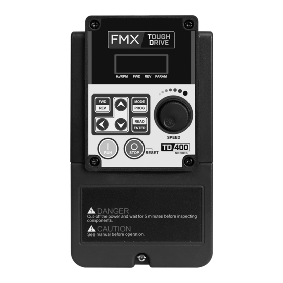
- Page 34 4. User Interface and Programming 4.1 LED Keypad 4.1.1 LED Keypad Display and Keys LED Display Forward Direction Status Indicator Reverse Direction Status Indicator 8 button Frequency Membrane Potentiometer Keypad Run Key Stop/Reset Key DISPLAY Description 5 Digit LED Display Monitor AC Drive signals, view / edit parameters, fault / alarm display. LED INDICATORS Hz/RPM LED ON when frequency or line speed is displayed.
- Page 35 4.1.2 Display Description Actual LED Display Actual LED Display Actual LED Display Actual LED Display ° LED lights on LED flashes Flashing digit At power-up the display will show the frequency reference setting; all LEDs are flashing. Use the keypad potentiometer to adjust set frequency.
- Page 36 Seven Segment display Description 1. Displays the frequency reference at power-up 2. Displays the actual output frequency in run operation. Displays parameter code Displays the setting value of parameter Displays input voltage class (note) Displays AC Drive current. Displays DC Bus Voltage Displays temperature Displays PID feedback value.
- Page 37 4.1.3 LED Status Description Hz/RPM LED State Description Hz/RPM LED Display doesn’t show frequency or line speed Illuminated Display shows frequency or line speed FWD LED State Description Forward LED AC Drive in reverse direction Illuminated AC Drive is running in forward direction Flashing Forward direction active, no run command REV LED...
- Page 38 4.1.4 Operation Control Stopped Running Stopping Stopped Output Frequency Indicator Indicator...
- Page 39 4.1.5 Using the Keypad Drive Monitoring The TD400 offers several monitoring functions that can be accessed by pressing the MODE/PROG key on the keypad repeatedly to cycle through the available monitors. The diagram below shows the default sequence of monitors in the TD400 drive. See parameter 12-00 details for instructions on how to change the monitor sequence or add/remove monitors from the sequence.
- Page 40 Parameter Programming Example The TD400 can be programmed directly from the keypad. Step Display The example below shows how to make changes to a parameter setting. For a complete list of parameters, see section 4.2. 5. Press LEFT key twice to select This example we will be setting the motor FLA (02-01 Rated far right digit.
- Page 41 4.2 Parameter Summary Parameter group Name Group 00 Basic Parameters Group 01 V/F Control Parameters Group 02 Motor Parameters Group 03 External Digital Input and Output Parameters Group 04 External Analog Input and Output Parameters Group 05 Preset Frequency Parameters Group 06 Automatic Program Operation Parameters Group 07...
- Page 42 Group 00 Basic Parameters Control mode Param. Parameter Name Setting Range Default Unit Notes PM/SLV 0: V/F 00-00 Control Mode Selection 2: SLV 5: PMSLV 0: Forward Motor’s Rotation 00-01 Direction 1: Reverse 0: Keypad 1: External Terminal (Control Circuit) Main Run Command ...
- Page 43 Group 00 Basic Parameters Control Mode Param. Parameter Name Setting Range Default Unit Notes SLV PM/SLV 00-13 Frequency Lower Limit 0.00-599.99 (Note) 00-14 Acceleration Time 1 0.1–6000.0 00-15 Deceleration Time 1 0.1–6000.0 ...
- Page 44 Group 01 Basic Motor Parameters Control Mode Param. Parameter Name Setting Range Default Unit Notes SLV PM/SLV 01-00 V/F Curve Motor 1 0–FF *3, (Note) 01-02 Maximum Output Frequency Motor 1 4.8–599.0 50.0/60.0 240V: 0.1–255.0 01-03 Maximum Output Voltage Motor 1 480V: 0.2–510.0...
- Page 45 Group 02 IM Motor Parameters Control Mode Param. Parameter Name Setting Range Default Unit Notes SLV PM/SLV 02-00 No-Load Current Motor 1 0.01–600.00 V/F mode: 10%–200% of AC Drive rated current. 02-01 Rated Current Motor 1 SLV mode: 25%–200% of AC Drive rated current.
- Page 46 Group 03 External Digital Input and Output Parameters Control Mode Param. Parameter Name Default Setting Range Unit Notes SLV PM/SLV 0: Forward/Stop Command 1: Reverse/Stop Command 2: Multi-Speed/Position Setting Command 1 Multifunction Input 03-00 3: Multi-Speed/Position Setting Terminal S1 Command 2 4: Multi-Speed/Position Setting Command 3 5: Multi-Speed/Position Setting...
- Page 47 Group 03 External Digital Input and Output Parameters Control mode Param. Parameter Name Setting Range Default Unit Notes SLV PM/SLV 03-08 1–200 S1-S6 scan time xxx0b: S1 A Contact xxx1b: S1 B Contact xx0xb: S2 A Contact xx1xb: S2 B Contact S1–...
- Page 48 Group 03 External Digital Input and Output Parameters Control mode Param. Parameter Name Setting Range Default Unit Notes SLV PM/SLV 03-13 Freq. Detection Level 0.0–599.0 03-14 Freq. Detection Width 0.1–25.5 03-15 Current Agree Level 0.1–999.9 Current Agree Detection...
- Page 49 Group 04 Analog signal inputs / Analog output Control Mode Param. Parameter Name Setting Range Default Unit Notes SLV PM/SLV 0: AI1 0–10V / 0–20mA AI2 0–10V / 0–20mA 1: AI1 0–10V / 0–20mA AI2 2–10V / 4–20mA ...
- Page 50 Group 05 Preset Frequency Selection Control mode Param. Parameter Name Setting Range Default Unit Notes PMSLV 0: Accel/Decel 1–4 apply to all speeds Preset Speed Control 05-00 1: Individual Accel/Decel for each Mode Selection preset speed ...
- Page 51 Group 05 Preset Frequency Selection Control mode Param. Parameter Name Setting Range Default Unit Notes SLV PMSLV 05-33 Preset Speed 8-Acc time 0.1–6000.0 05-34 Preset Speed 8-Dec time 0.1–6000.0 05-35 Preset Speed 9-Acc time 0.1–6000.0 ...
- Page 52 Group 06 Automatic Program Operation Control mode Param. Parameter Name Setting Range Default Unit Notes PMSLV Frequency Setting 06-04 0.00–599.00 *1, (Note) Operation-Stage 4 Frequency Setting 06-05 0.00–599.00 *1, (Note) Operation-Stage 5 Frequency Setting 06-06 0.00–599.00 *1, (Note)
- Page 53 Group 06 Automatic Program Operation Control mode Param. Parameter Name Setting Range Default Unit Notes PMSLV 0: Stop Operation Direction 06-32 1: Forward Speed Stage 0 2: Reverse 0: Stop Operation Direction 06-33 1: Forward Speed Stage 1 2: Reverse 0: Stop Operation Direction...
- Page 54 Group 07 Start/Stop Parameters Control mode Param. Parameter Name Setting Range Default Unit Notes PMSLV 0: Disable Momentary Power Loss 07-00 and Restart 1: Enable 07-01 Fault Reset Time 0–7200 Number of Auto Restart ...
- Page 55 Group 07 Start/Stop Parameters Control mode Param. Parameter Name Setting Range Default Unit Notes PMSLV Low Voltage Detection 07-25 0.00–1.00 0.02 Time SLV Coast to Stop 0: Start With Speed Search 07-26 Start-up Mode Selection 1: Normal Start Start after Fault During 0: Start With Speed Search ...
- Page 56 Group 08 Protection Parameters Control mode Param. Parameter Name Setting Range Default Unit Notes xxx0b: Overload Protection is disabled. xxx1b: Overload Protection is enabled. V/F & xx0xb: Cold Start of Motor Overload SLV: xx1xb: Hot Start of Motor Overload 0001b Motor Overload ...
- Page 57 Group 08 Protection Parameters Control mode Param. Parameter Name Setting Range Default Unit Notes PMSLV PTC Input Filter Time 08-36 0.00 – 5.00 Constant 08-38 Delay Time Fan Off 0–600 Delay Time Motor ...
- Page 58 Group 09 Communication Parameters Control mode Param. Parameter Name Setting Range Default Unit Notes PMSLV Communication Station 09-00 1–254 *3, (note) Address 0: MODBUS Communication Mode *3,*5, 09-01 Selection (note) 2: BACnet 0: 4800 1: 9600 ...
- Page 59 Group 10 PID Parameters Control Mode Param. Parameters Setting Range Default Unit Notes PMSLV 0: Keypad Potentiometer 1: AI1 Input PID Target Value Source 10-00 2: AI2 Input Setting 3: Communication 4: Target Source set by 10-02 0: Keypad Potentiometer 1: AI1 Input PID Feedback Value...
- Page 60 Group 10 PID Parameters Control Mode Param. Parameters Setting Range Default Unit Notes PMSLV 0: Disable 10-29 PID Sleep Selection 1: Enable 2: Set By DI 10-30 Upper Limit PID Target 0.0 – 100.0 ...
- Page 61 Group 11 Auxiliary Parameters Control Mode Param. Parameters Setting Range Default Unit Notes PMSLV 0: Allow For. and Rev. Rotation 11-00 Direction Lock Selection 1: Only Allow Forward Rotation 2: Only Allow Reverse Rotation 0: Carrier Output Frequency Tuning ...
- Page 62 Group 11 Auxiliary Parameters Control Mode Param. Parameters Setting Range Default Unit Notes PMSLV OV Prevention 11-37 0.00 – 599.00 5.00 Frequency Limit 240V: 240V–400V OV Prevention Decel. 11-38 Start Voltage 480V: 400V–800V 240V: 300V–400V OV Prevention Decel. ...
- Page 63 Group 12 Monitoring Parameters Control Mode Param. Parameters Setting Range Default Unit Notes PMSLV 00000–88888 From the leftmost bit, sets the display sequence when pressing the MODE/PROG key. 0: no display 1: Output Current 12-00 Display Screen (LED) 2: Output Voltage 3: DC Bus Voltage 4: Heatsink Temperature*...
- Page 64 Group 12 Monitoring Parameters Control Mode Param. Parameters Setting Range Default Unit Notes PMSLV 12-06 Output Current Display the present output current 12-07 Output Power Display the present output power Output Current of Display the output current of current ...
- Page 65 Group 13 Maintenance Parameters Control Mode Param. Parameters Setting Range Default Unit Notes PMSLV 13-00 AC Drive Capacity ---- 13-01 Software Version ---- 13-02 Fault Record ---- 13-03 Hour Meter 1 0–23 ...
- Page 66 Group 14 PLC Setting Parameters Control Mode Param. Parameters Setting Range Default Unit Notes PMSLV 14-08 T5 Set Value 1 0–9999 14-09 T5 Set Value 2 (Mode 7) 0–9999 14-10 T6 Set Value 1 0–9999 ...
- Page 67 Group 15 PLC Monitoring Parameters Control Mode Param. Parameters Setting Range Default Unit Notes PMSLV 15-00 T1 Current Value1 0–9999 T1 Current Value 2 15-01 0–9999 (Mode7) 15-02 T2 Current Value 1 0–9999 T2 Current Value 2 ...
- Page 68 Group 16 LCD Keypad Parameters Control Mode Param. Parameters Setting Range Default Unit Notes PMSLV 5–39 when using LCD to operate, the 16-00 Main Screen Monitoring monitored item displays in the first line. (default is frequency command) 5–39 when using LCD to operate, the ...
- Page 69 Group 16 LCD Keypad Parameters Control Mode Param. Parameters Setting Range Default Unit Notes PMSLV 16-05 LCD Backlight 0–7 0: Do not copy parameters 1: Read AC Drive parameters and store parameters settings in the operator. ...
- Page 70 Group 17 Automatic Tuning Parameters Control Mode Param. Parameter Name Setting Range Default Unit Notes PMSLV 0: No error 1: Motor data error 2: Stator resistance tuning error 3: Leakage induction tuning error 4: Rotor resistance tuning error Automatic Tuning Error ...
- Page 71 Group 20 Speed Control Parameters Control Mode Param. Parameters Setting Range Default Unit Notes PMSLV SLV: 6 20-00 ASR Gain 1 0.00–250.00 PMSLV: 3 SLV: 0.5 20-01 ASR Integral Time 1 0.001–10.000 PMSLV: 0.08 SLV: 6 ...
- Page 72 Group 21 Torque And Position Control Parameters Control mode Param. Parameters Setting Range Default Unit Notes PMSLV 21-05 Positive Torque Limit 0–300 21-06 Negative Torque Limit 0–300 Forward Regenerative 21-07 0–300 Torque Limit Reversal Regenerative ...
- Page 73 4.2.1: Parameter default values and ranges depending on AC Drive model The maximum The maximum Maximum Output Maximum Output Factory setting value of 11-01 value of 11-01 Frequency (Hz) in Frequency (Hz) in Model Frame of 11-01 in in HD mode in HD mode SLV Mode when SLV Mode when...
- Page 74 Heat Sink SLV default value Default value Default value Default value Temperature (18-00) Model of 21-05–21-08 of 20-08 (ASR of 00-14–00-17 Displayed, (Low speed slip (Torque limit) delay time) 00-21–00-24 Parameter 12-41 compensation) 20P5 200% 0.001 2001 2002 2003 200% 0.001 2005 27P5...
- Page 75 4.3 Parameter Details 00 Basic Parameters 00-00 Control Mode Selection Default: 0 【0】: V/F 【2】: SLV Range 【5】: PMSLV The AC Drive offers the following control modes: 00-00=0: V/F Mode without encoder For the quickest out-of-box setup or when controlling multiple motors from on AC drive, use V/F mode. V/F mode is ideal for loads where precise speed regulation is not needed (regulation is approximately 2-3% of set speed).
- Page 76 00-01 Motor’s Rotation Direction Default: 0 【0】: Forward Range 【1】: Reverse Use the FWD/REV key to change motor direction when Run Command (00-02 = 0) is set to keypad control. 00-02 Main Run Command Source Default: 2 【0】: Keypad 【1】: External Terminal (Control Circuit) Range 【2】: Communication Control (RS-485) 【3】: PLC...
- Page 77 00-04 Operation Modes for External Terminals Default: 0 【0】: Forward/Stop-Reverse/Stop 【1】: Run/Stop- Reverse/ Forward Range 【2】: 3 Wire Control Mode - Run/Stop Note: 00-04 is valid when run command is set to external mode by 00-02/00-03 =1. 2 Wire Operation Mode, Set 00-04 to【0】or【1】first, before setting 03-00 (S1 terminal selection) to 0 and 03-01 (S2 terminal selection) to 1 Forward Terminal S1...
- Page 78 Param. # Parameter Name Default Range 【0】: Up/Down on Keypad 【1】: Potentiometer on Keypad 00-05 Main Frequency Command Source Selection 【2】: External AI1 Analog Signal Input 【3】: External AI2 Analog Signal Input 【4】: External Up/Down Frequency Control 【5】: Communication Setting Frequency 00-06 Alternative Frequency Source Selection 【6】: Reserved...
- Page 79 00-05/00-06= 4: Terminal UP / DOWN The AC Drive accelerates with the UP command active and decelerates with the DOWN command active. Please refer to parameter 03-00 – 03-05 for additional information. Note: To use this function both the UP and DOWN command have to be set to any of the input terminals. 00-05/00-06= 5: Communication Control The frequency reference command is set via the RS-485 communication port.
- Page 80 00-09 Communication Frequency Command Memory Default: 0 【0】: Do not store the communication frequency at power down Range 【1】:Store communication frequency at power down Note: This parameter is only active when frequency reference is set via communication (00-05 / 00-06) 00-10 Initial Frequency Selection Default: 0...
- Page 81 00-14 Acceleration Time 1 Default: – 【0.1–6000.0】Sec Range 00-15 Deceleration Time 1 Default: – 【0.1–6000.0】Sec Range 00-16 Acceleration Time 2 Default: – 【0.1–6000.0】Sec Range 00-17 Deceleration Time 2 Default: – 【0.1–6000.0】Sec Range Acceleration and deceleration times are represented by the three most significant (high order) digits. Set acceleration and deceleration times with respect to maximum frequency.
- Page 82 A: Select acceleration and deceleration time via the digital input terminals The following table shows the acceleration / deceleration selected when the digital input function Accel / Decel time 1 is used. Tdec2 Rate Tacc2 Output Accel/Decel Rate Frequency time 1 Acceleration Tdec1 Deceleration Time...
- Page 83 00-26 Emergency Stop Time Default: 5 【0.1–3600.0】Sec Range The emergency stop time is used in combination with multi-function digital input Emergency Stop function #14 (Emergency stop) or #15 Command Time (Base block). When emergency stop input S5(03-04=14) is activated the AC Drive will decelerate to a stop using the Emergency stop time (00- 26).
- Page 84 00-34 Language Default: 0 【0】English 【1】Simplified Chinese Range 【2】Traditional Chinese 【3】Turkish LCD keypad is required to display languages. Selection of parameter 00-34 00-34=0: LCD keypad displays in English. 00-34=1: LCD keypad displays in Simplified Chinese. 00-34=2: LCD keypad displays in Traditional Chinese. 00-04=3: LCD keypad displays in Turkish.
- Page 85 01 V/F Control Parameters 01-00 Volts/Hz Patterns Default: F 【0–FF】 Range The V/F curve selection is enabled for V/F mode. Make sure to set the AC Drive input voltage parameter 01-14. There are three ways to set V/F curve: (1) 01-00 = 0 to 0E: choose any of the 15 predefined curves (0 to 17). (2) 01-00 = 0F, use 01-02 to 01-09 and 01-12 to 01-13, with voltage limit (2) 01-00 = FF, use 01-02 to 01-09 and 01-12 to 01-13, without voltage limit Custom curves F and FF use identical curves to 0 (for 50Hz) or 1 (for 60Hz) as a baseline.
- Page 86 2P5 – 2HP V/F curve selection Type 01-00 Specification V/F curve 01-00 Specification V/F curve (V%) (V%) Starting (01-14) (01-14) Torque (0),(F) 50Hz 50Hz High 7.3% (50Hz Starting 6.8% 3.7% Default) Torque 3.6% 3.65% (Hz) (Hz) 0 1.3 1.3 2.5 (V%) (V%) (01-14)
- Page 87 3 – 30HP V/F curve selection Type 01-00 Specification V/F curve 01-00 Specification V/F curve (V%) (V%) Starting (01-14) (01-14) Torque (0),(F) 50Hz 50Hz High 6.9% (50Hz Starting 6.6% 6.4% 3.5% Default) Torque 3.4% 3.4% (Hz) (Hz) 0 1.3 1.3 2.5 (V%) (V%) (01-14)
- Page 88 40HP and above V/F curve selection Type 01-00 Specification V/F curve 01-00 Specification V/F curve (V%) (V%) Starting (01-14) (01-14) Torque (0),(F) 50Hz 50Hz High 7.25% (50Hz 6.8% Starting 6.95% 4.1% Default) Torque 3.85% 3.85% (Hz) (Hz) 0 1.3 1.3 2.5 (V%) (V%) (01-14)
- Page 89 V/F curve setting Select any of the predefined V/F curves setting ‘0’ to ‘E’ that best matches your application and the load characteristic of your motor. Choose a custom curve setting ‘F’ or ‘FF’ to set a custom curve. 01-02 Maximum frequency output motor 1 Default: 50.0/60.0 【4.8–599.0】Hz...
- Page 90 The value for maximum output voltage of the motor 1 (01-03) and the value for base output voltage of the motor (01-13) will depend on the setting of 13-08 which sets the value of voltage upon initialization. When the control mode is changed in parameter 00-00, 01-08 (Fmin) and 01-09 (Vmin) will be automatically changed to the default setting of the selected control mode.
- Page 91 SLV Mode (Sensorless Vector Control) Enter the motor data in parameter group 17 for SLV control mode (00-00) and perform auto-tuning. In SLV mode, the V/F curve normally does not have to be re-adjusted after a successful auto-tune. The maximum output frequency setting 01-02 (Fmax), base frequency 01-12 (Fbase), minimum output frequency 01- 08 (Fmin), maximum output voltage 01-03 (Vmax) or base output voltage 01-13 (Vbase) can be manually adjusted but the voltage is automatically adjusted by the internal current controller.
- Page 92 Torque compensation gain (01-10) can be adjusted at run time. Gradually change torque boost value to ensure output current does not exceed AC Drive rated current. Increase Value When: Reduce Value When: • Wire length between AC Drive and motor is too long •...
- Page 93 01-15 Torque compensation time Default: 200 【0–10000】ms Range Set the torque compensation delay time in milliseconds. Only adjust in the following situations: • Increase the value when experiencing motor vibration. • Decrease the value when motor torque response is too slow. 01-16 Maximum output frequency of motor 2 Default: 50.0/60.0...
- Page 94 02 IM Motor Parameters 02-00 No-load current motor 1 Default: – 【0.01–600.00】A Range 02-01 Rated current motor 1 Default: – V/F mode is 10%–200% of AC Drive rated current Range SLV mode is 25%–200% of AC Drive rated current 02-03 Rated rotation speed motor 1 Default: –...
- Page 95 02-04: Motor rated voltage Set the motor rated voltage according to the motor nameplate. Set the motor rated voltage and it will adjust maximum output voltage of V/F curve. 02-05: Motor rated power The nominal motor rated capacity is set at the factory. Please verify that the motor name plate data matches the motor rated capacity shown in parameter 02-05.
- Page 96 02-15 Line-to-line Resistance of motor 1 Default: – 【1–60.000】Ω Range 02-17 Leakage Inductance Motor 1 Default: – 【0.01–200.00】mH Range 02-19 No-Load Voltage of motor 1 Default: – 【0.01–600.00】A Range 02-20 No-Load Current of motor 2 Default: – 【0.01–600.00】A Range 02-21 Rated current of motor 2 Default: –...
- Page 97 02-33: Proportion of Motor Leakage Inductance 1. In most applications motor leakage current does not need to be adjusted. The value is not set by the auto-tuning function. LlKg ξ 2. Leakage inductance proportion is the ratio between leakage inductance and rotor inductance. The default value is set to 3.4%.
- Page 98 03 External Digital Input and Output Parameters Multi-function digital input and related parameters Param. # Parameter Name Default Range 0: Forward/Stop Command 1: Reverse/Stop Command 2: Multi-Speed/Position Setting Command 1 03-00 Multifunction Input Terminal S1 3: Multi-Speed/Position Setting Command 2 4: Multi-Speed/Position Setting Command 3 5: Multi-Speed/Position Setting Command 4 6: Forward Jog Run Command...
- Page 99 Related Parameters 03-00 03-01 03-02 03-03 03-04 03-05 24VG Multi-function digital input settings (03-00 to 03-05): “O” Available, “X” Not Available Function Control Mode Value Description Name LCD Display SLV PM/SLV 2-Wire (FWD- 2- wire Forward/Stop command Forward/Stop command RUN) (ON: Forward operation command).
- Page 100 Function Control Mode Value Description Name LCD Display SLV PM/SLV PID control disabled PID Disable ON: PID control disabled Fault reset (Reset) Fault Reset ON: Fault reset Auto Run Mode Enable ON: Auto run mode enabled (06-00) ON: Speed search from the Speed Search Speed Search 1 maximum output frequency...
- Page 101 03-0X =02: Multi-speed/position setting command 1 03-0X =03: Multi-speed/position setting command 2 03-0X =04: Multi-speed/position setting command 3 03-0X =05: Multi-speed/position setting command 4 Multi-speed operation selection Multi-function digital input (S1 to S6)*1 Speed Frequency selection Multi-speed Multi-speed Multi-speed Multi-speed frequency frequency 4 frequency 3...
- Page 102 03-0X =06: Forward jog run command, uses jog frequency parameter 00-18. 03-0X =07: Reverse jog run command, uses jog frequency parameter 00-18. 03-0X =08: UP frequency command 03-0X =09: Down frequency command AC Drive can use the digital operator and external digital input (S1–S6) to increase or decrease output frequency while motor is running.
- Page 103 UP / DOWN Command Operation When the Forward Run command is active and the UP or Down command is momentarily activated the AC Drive will accelerate the motor up to the lower limit of the frequency reference (00-13). When using the UP / Down command, the output frequency is limited to the upper limit of frequency reference (00-12) and the lower limit of frequency reference (00-13).
- Page 104 03-0X =14: Emergency stop (decelerate to zero and stop) Refer to the "deceleration time of emergency stop" of parameter 00-26 Emergency stop switch wired to the S terminal that is set to 14 will trigger a deceleration to zero according to the speed set in parameter 00-26 and then stop.
- Page 105 03-0X =18: Auto run mode enable When input is active, auto run mode function is enabled. Please refer to group 06 for more information. 03-0X =19: Speed Search 1 (from the maximum frequency). See parameter 07-10 details. 03-0X =34: Speed Search 2 (from the frequency command). See parameter 07-10 details. 03-0X =20: Energy saving enabled when input is active.
- Page 106 Example: To use the pulse input as a speed reference set the following parameters: 00=05=7, 03-0X=26,X=0–6 (except select 2), 03-31=pulse input frequency 03-32=100.0 (adjust as required) Pulse input frequency is 200Hz, set 03-31=0.20kHz. Example 1: Pulse input frequency is 200Hz (03-31=0.20), duty cycle is 50%, frequency upper limit is 50Hz (00-12=50.00), and 03-32=100.0.
- Page 107 Set one of 03-00 to 03-05 = 27 Keypad Local Mode Frequency Reference Run Command RS-422/RS-485 communications Remote Mode Control circuit terminals Set one of 03-00 to 03-05 = 28 4-74...
- Page 108 03-0X =33: DC braking When input is active, DC-Injection braking is enabled during starting and stopping of the AC Drive. DC Injection braking is disabled when a run or jog command is active. Refer to the DC braking time diagram below. Run Or Jog Command DC injection...
- Page 109 03-0X =66: PID control disabled. 03-0X=68: External Fault Activating the external fault input will turn off the AC Drive output and the motor will coast to a stop. The keypad displays the external fault message “EFn Ext. Fault (Sn)”, where n is the input terminal number. 03-0X=69: External Overload Used for an input for an external motor overload signal.
- Page 110 Functions of Multi-function Digital Output Param. # Parameter Name Default Range 【0】: During Running 【1】: Fault Contact Output 【2】: Frequency Agree 【3】: Setting Frequency Agree (03-13 ± 03-14) 【4】: Frequency Detection 1 (≥ 03-13, hysteresis range is the setting value of 03-14) 【5】: Frequency Detection 2 (≤...
- Page 111 Function Control mode Value Contents Name LCD display SLV PM/SLV ON:During running (Run command During Running Running is ON) ON:Fault contact output (except Fault Contact Output Fault CF00 and CF01) ON:Frequency agree (frequency Frequency Agree Freq. Agree agree width detection is set by 03- 14 ) ON:Output frequency = allowed Setting Frequency Agree...
- Page 112 03-1X=0: During Running ON: Run command is ON or output frequency is greater than 0 OFF: Run command is OFF and the AC Drive is stopped. 03-1X=1: Fault contact output Output is active during fault condition. Communication error (CF00, CF01) does not activate the fault contact. 03-1X=2: Frequency Agree Output is active when output frequency falls within frequency reference minus the frequency detection width (03-14).
- Page 113 03-1X=19: PLC control contact Output is controlled by the PLC logic 03-1X=20: Zero-speed Output is active during zero-speed when output frequency ≤ minimum output frequency (01-08). Output Frequency 01-08(Fmin) Zero Speed 03-1X=30: Motor 2 Selection Output is active when motor 2 is selected 03-1X=37: Detection Output of PID Feedback Loss Turns ON when PID feedback loss occurs.
- Page 114 Frequency Agree Detection Functions 03-13 Frequency detection level Default: 0 【0.0–599.0】Hz Range 03-14 Frequency detection width Default: 2 【0.1–25.5】Hz Range Frequency detection Level: set the multi-function output terminals R1A-R1C, R2A-R2C or PH1 (03-11, 03-12) to the desired detection level and bandwidth for use with multi-function output functions 1 to 6. The time charts for the Frequency Agree Detection operation are shown in the following table.
- Page 115 Function Frequency Detection Function Description Output is active when the output frequency rises above the 03-14 Output frequency detection level Frequency 03-13 (03-13) + frequency detection 03-13 width (03-14) and deactivates time when the output frequency falls Output frequency 03-14 below frequency detection level Output detection 1...
- Page 116 03-16: Output Current detection delay time ON: Output current has to rise above specified level (03-15) for time specified in 03-16. OFF: Output current has to fall below specified level (03-15) for time specified in 03-16. 100% I : Load current 03-15 03-16 Constant...
- Page 117 When 03-18≥03-17, the following sequence applies: 03-18 03-17 STOP 03-11=14 03-19 Relay (R1A-R2A) Type Default: 0000b xxx0b: R1 A contact xxx1b: R1 B contact Range xx0xb: R2 A contact xx1xb: R2 B contact Parameter 03-19 selects the digital output type between a normally open and a normally closed contact. Each bit of 03-19 represents an output: 03-19 = 0 0: normally open contact...
- Page 118 03-27=0: When the run command is removed, the External UP/DOWN frequency reference from before deceleration is stored. The next time the run command is applied, the output frequency will ramp up to the previously stored frequency reference. Adjustments to frequency reference can only be made after previously stored reference is reached. 03-27=1: When the run command is removed, the External UP/DOWN frequency reference command is cleared (set to 0).
- Page 119 Setup Pulse Input as Frequency Reference Set parameters 00-05 = 4 and 03-30 = 0 to use the pulse input terminal (PI) as the frequency reference source. Next set the pulse input scaling (03-31), enter the pulse input frequency to match the maximum output frequency. Adjust the pulse input filter time (03-34) in case interference or noise is encountered.
- Page 120 Descriptions: ΔH1: frequency increase during acceleration, t1: Multi-function input active time during acceleration, ΔH2: frequency increase during deceleration, t2: Multi-function input active time during deceleration. Upper Limit Frequency ΔH1 i t l Accelerati Lower Limit Frequency ΔH2 i t l Decelerati 04 Analog Signal Inputs / Analog Output 04-00...
- Page 121 Analog input signal type (04-00): •AI1 is 0–10V, switch JP2 of control board to V, set parameter 04-00 to 0 or 1. •AI1 is 2–10V, switch JP2 of control board to V, set parameter 04-00 to 2 or 3. •AI1 is 0–20mA, switch JP2 of control board to I, set parameter 04-00 to 0 or 1. •AI1 is 4–20mA, switch JP2 of control board to I, set parameter 04-00 to 2 or 3.
- Page 122 (2) AI1 signal filtering time (04-01) (3) AI2 signal filtering time (04-06) All analog inputs (AI1, AI2) have a 1st order programmable input filter that can be adjusted when noise is present on each of the incoming analog signal to prevent erratic drive control. The filter time constant (range: 0.00 to 2.00 seconds) is defined as the time that the input step signal reaches 63% of its final value.
- Page 123 Analog output AO adjustment (04-12, 04-13 Analog Output Signal and 04-15) 10V(or 20mA) Signal: Use parameter 04-11 to select the × Gain analog output signal for AO. (20mA) 10V Gain: Use parameter 04-12 to adjust the gain for AO. Adjust the gain so that the analog output (10V) matches 100% of the selected analog output signal (04-11 for AO).
- Page 124 Frequency 200Hz upper limit (Hz) 100Hz C 50Hz Analog Input Signal Master 04-25 AO Voltage Auto Tuning Default: 0 【0】: Disable Range 【1】: Enable Parameter 04-25 can be used to compensate for innacuracies in the analog output. These may be caused by voltage drop or impedance mismatch between the AC drive and the other device.
- Page 125 Param. # Parameter Name Default Range 05-14 Preset Speed 13 【0.00 – 599.00】 Hz 05-15 Preset Speed 14 05-16 Preset Speed 15 05-17 Preset Speed 0 Acceleration time 05-18 Preset Speed 0 Deceleration time 05-19 Preset Speed 1 Acceleration time 05-20 Preset Speed 1 Deceleration time 05-21...
- Page 126 Maximum output frequency: Parameter 01-00=F, maximum output frequency set by 01-02, 01-00 ≠ F, maximum output frequency determined by V/F curve selected (50.0 / 60.0 / 90.0 / 120.0 / 180.0). Example: 01-00=0 (50Hz (maximum output frequency), 05-02=10 Hz (multi-step speed 0), 05-17=5.0s (Acceleration time), 05-18=20.0 sec.
- Page 127 Acceleration / Deceleration Calculation Mode 2: If the run command remains on, acceleration and deceleration time (a – f) are calculated based on the active speed command as follows: 06-02 06-01 06-03 06-05 05-01 06-04 Stop Terminal S1 Terminal S2 Terminal S3 Terminal S4 Terminal S5...
- Page 128 06 Automatic Program Operation 06- 00 Auto Run Mode Select Default: 0 【0】: Disabled 【1】: Execute a single cycle operation. Restart speed is based on the previous stopped speed. 【2】: Execute continuous cycle operation. Restart speed is based on the previous cycle stop speed. 【3】: After completion of a single cycle, the on-going operation speed is based on the speed of the Range last stage.
- Page 129 Param. # Parameter Name Default Range Operation direction speed-stage 0 06-32 Operation direction speed-stage 1 06-33 06-34 Operation direction speed-stage 2 Operation direction speed-stage 3 06-35 Operation direction speed-stage 4 06-36 Operation direction speed-stage 5 06-37 Operation direction speed-stage 6 06-38 【0】: Stop Operation direction speed-stage 7...
- Page 130 Example 1: Automatic operation mode – Single cycle In this example the AC Drive executes a single cycle and then stops. Parameter Settings: 06-00 = 1 or 4 (Single cycle operation) 06-32–06-34= 1 (Forward for multi-step speed 0 - 2) 06-47= 2 (Reversal for multi-step speed 15) 06-35–06-46=...
- Page 131 Example 2: Automatic operation mode – Continuous cycle In this example the AC Drive repeats the same cycle. Parameter Settings: 06-00 = 2 or 5 (Continuous cycle operation) 06-01 to 06-47= Enter same setting as that of Example 1. Freq. 06-02 06-02 50 Hz...
- Page 132 06-00= 1 to 3: After a stop the AC Drive will start with the incomplete step when run command is re-applied. 06-00= 4 to 6: After a stop the AC Drive will start with the first step of the cycle when run command is re-applied. 06-00 1 to 3 06-00...
- Page 133 The automatic restart function can be used for the following faults. Please note that if the fault is not listed in the table, the AC Drive will not attempt an automatic restart. Fault Code Description Number of Restarts Under voltage Unlimited Over current (07-02)
- Page 134 Note: Multi-function digital output R1A-R1C, R2A-R2C can be programmed to activate during an automatic reset attempt, refer to parameter 03-11 or 03-12, function 06. Automatic restart operation: AC Drive trips and AC Drive output is turned off, keypad shows the active fault. Next, AC Drive waits for the minimum baseblock time parameter 07-18 to expire before accepting an automatic restart command.
- Page 135 07-06 DC Injection Braking Start Frequency Default: 1.5 【0.0–10.0】: Hz Range DC Injection braking functionality depends on the selected control mode (00-00), please refer to the description below for each control mode. V/f or SLV Control mode (00-00 = 0, 2): DC Injection Brake Start Frequency parameter (07-06) is the level the output frequency has to reach before DC braking injection function is de-activated at start and activated at stop.
- Page 136 Note: • When 07-06 < 01-08, DC injection braking starting frequency becomes frequency set in parameter 01-08. • Continuous use of short-circuit braking may damage internal IGBTs. • Short-circuit braking is controlled by multi-function input option 65. 07-07 DC Injection Braking Level Default: 50 【0–100】% Range...
- Page 137 Command Stop Time Deceleration ramp to stop Output Frequency 07-06 Time T:DC braking time at stop (07-08) 07-09 =1: Coast to stop When a stop command is issued, the motor will Stop coast to a stop. Stop time depends on motor Command Time load and friction of the system.
- Page 138 07-09 =3: Coast to stop with timer When a stop command is issued the motor will coast to a stop after the minimum Baseblock time (07-18) has expired and the AC Drive ignores the run command until the timer has expired. The total time of the timer is determined by the deceleration time (00-15, 17, 22 or 24) and the output frequency upon stop.
- Page 139 07-15 DC Injection Brake Mode Default: 1 【0】: Voltage Mode Range 【1】: Current Mode 07-18 Minimum base block time Default: – 【0.1–5.0】Sec Range During a momentary power failure, the AC Drive continues to operate after power has been restored when parameter 07-00 is set to 1.
- Page 140 Speed search function is used to find the speed of a coasting motor and continue operation from that point. The speed search function is active after a momentary power loss. Speed Search from Multi-function digital inputs Set the multi-function digital input to external speed search command 1 or 2. External speed search command 1 (value = 19) and 2 (value = 34) cannot be set at the same time, otherwise "SE02"...
- Page 141 07-24: Direction-Detection Speed Search Selection 0: Disable Direction-Detection Speed Search Speed search is executed using speed search operating current defined in parameter 07-20. In case speed search is not successful (e.g. motor speed is too low) a speed search time-out warning is displayed. Set 07-19 to value greater than 0 to enable DC braking at speed search if a time-out occurs frequently.
- Page 142 Notes: If the minimum base block time (07-18) is longer than the momentary power failure time, the speed search starts operation after the minimum base block time (07-18). If the minimum base block time (07-18) is too short, the speed search operation begins immediately after power has been restored.
- Page 143 07-37 Pre-excitation time Default: 2 【0.00–10.00】Sec Range 07-38 Pre-excitation initial level Default: 100 【50–200】% Range If a high starting torque is required for the application, especially for large horsepower motors, the pre-excitation operation can be used to pre-flux (magnetize) the motor. 07-37 Pre-excitation time When an operation command (forward or reverse) is activated, the AC Drive will automatically start pre-excitation based...
- Page 144 08 Protection Parameters 08-00 Stall prevention function Default: 0000b 【xxx0b】: Stall prevention function is enabled during acceleration. 【xxx1b】: Stall prevention function is disabled during acceleration. 【xx0xb】: Stall prevention function is enabled during deceleration. 【xx1xb】: Stall prevention function is disabled during deceleration. Range 【x0xxb】: Stall prevention function is enabled during operation.
- Page 145 Stall prevention during deceleration (08-00=xx0xb) Stall prevention during deceleration automatically increases the deceleration time based on the DC-bus voltage to prevent over-voltage during deceleration. Refer to figure below for stall prevention during deceleration When the DC-bus voltage exceeds the stall prevention level, deceleration will stop and the AC Drive will wait for the DC-bus voltage to fall below the stall prevention level before continuing deceleration.
- Page 146 08-05 Motor overload protection (OL1) Default: 0001b 【xxx0b】: Motor overload is disabled 【xxx1b】: Motor overload is enabled 【xx0xb】: Cold start of motor overload 【xx1xb】: Hot start of motor overload Range 【x0xxb】: Standard motor 【x1xxb】: Special motor 【0xxxb】: Reserved 【1xxxb】: Reserved The motor overload protection function estimates the motor overload level based on the output current, output frequency, motor characteristics and time.
- Page 147 When using force cooled motors (Special AC Drive motor), thermal characteristics are independent of the motor speed, set 08-05 = x1xxb. When 08-05 = x1xxb, overload protection function is based on motor rated current for output frequencies between 6 and 60Hz. If the output frequency is less than 1Hz, the overload protection function uses 83% of the motor rated current to determine an overload condition.
- Page 148 08-08 Automatic voltage regulation (AVR) Default: 0 【0】: AVR enabled Range 【1】: AVR disabled Automatic voltage regulation stabilizes the motor voltage independent of fluctuation to the input voltage. 08-08=0: Automatic voltage regulation is active. It will limit the maximum output voltage. When three-phase input voltage fluctuates and the voltage is smaller than the value of 01-14, the output voltage will fluctuate in sync with the input voltage.
- Page 149 Parameter 08-13 selects over-torque detection function. An over-torque condition is detected when the output current / torque rises above the level set in parameter 08-15 (Over-torque detection level) for the time specified in parameter 08-16 (Over-torque detection time). 08-13=0: Over-torque detection is disabled. 08-13=1: Over-torque detection is enabled when the output frequency reaches the set frequency.
- Page 150 08-21 Limit of stall prevention during acceleration Default: 50 【1–100】% Range 08-22 Stall prevention detection time during run Default: 100 【2–100】ms Range Parameter 08-21 is the stall prevention limit value in Constant Horsepower region. Refer to figure below. 08-01 Stall prevention level during acceleration...
- Page 151 08-35=1 or 2: The AC Drive will display [OH4 Motor Temp Warning] when the motor temperature increases and AI2 voltage level rises above the value set in 08-44. In this condition the motor will decelerate or coast to stop depending on setting 08-35=1 or 2.
- Page 152 Fire Mode (Run-at-all-Costs Mode) Warning: Use of this mode for any application must be considered carefully and all safety implications must be taken into account. When enabled and Fire Mode is activated (See multi-function digital inputs, 03-05=【28】), all protection features of the AC Drive will be disabled and the unit will continue to operate until its possible destruction. All liabilities for the use of this function will remain user’s responsibility.
- Page 153 09 Communication Parameters 09-00 Communication Station Address Default: 1 【1–32】 Range 09-01 Communication Mode Selection Default: 0 【0】: MODBUS Range 【2】: BACnet 09-02 Baud Rate Setting (bps) Default: 2 【0】: 4800 【1】: 9600 Range 【2】: 19200 【3】: 38400 09-03 Stop Bit Selection Default: 0 【0】: 1 stop bit Range...
- Page 154 09-09: AC Drive Transmission Wait Time (09-09). This is the time between the controller message and the start of the AC Drive response message. Refer to Figure below. Set the controller receive time-out to a greater value than the wait time parameter. Master AC Drive AC Drive...
- Page 155 Parameter 10-01 sets the PID feedback value source. This value is what the PID function will use to determine needed output. PID setting point Keypad display: 10-00=0 Analog Input 1: 10-00=1 Target Analog Input 2: 10-00=2 10-26 Value Communication: 10-00=3 PID target PID Target Value (10-02): 10-00=4 10-00 ≠...
- Page 156 Feedback (detected value) is derivative controlled and set by parameter 10-07. Make sure to adjust the PID parameters without causing system instability. Refer to Figure above for PID control for feedback value differential. For 10-03 = 0001b or 0010b, if error signal (target minus feedback) is positive, output frequency increases and vice versa. For 10-03 = 0011b or 0100b, if error signal (target minus feedback) is positive, output frequency decreases and vice versa.
- Page 157 10-07 Differential time (D) Default: 0 【0.00–10.00】Sec Range 10-07 Differential control: This control is the inverse from integral control and tries to guess the behavior of the error signal by multiplying the error with the differential time. The result is added to the PID input. Differential control slows down the PID controller response and may reduce system oscillation.
- Page 158 PID Control Flow (Bias) PID=OFF 10-09 10-03=1xxxb +109% ±200% Limit 10-25=0 10-03=xx0xb + PID output gain ×1 Frequency PID=0N 10-24 reference 10-03=0xxxb +109% 10-03=xx1xb 10-25=1 PID Output -109% 10-00=2 PID=OFF 1. 10-03=0 (PID disabled) 10-00=4 10-00=1 2. During JOG mode 10-02 3.
- Page 159 PID feedback loss detection 10-11 PID feedback loss detection selection Default: 0 【0】: Disabled 【1】: Warning Range 【2】: Fault 10-12 PID feedback loss detection level Default: 0 【0–100】% Range 10-13 PID feedback loss detection delay time Default: 1 【0.0–10.0】Sec Range The PID control function provides closed-loop system control.
- Page 160 10-16 PID Integrator Reset Deviation Range Default: 0 【0–100】% Range Parameter sets the percent difference PID feedback value must be from PID setpoint for the integrator to restart. There is a ± 5% tolerance. PID Sleep Parameters 10-17 PID Sleep Start Frequency Default: 0 【0.00–599.00】Hz Range...
- Page 161 10-23 PID limit Default: 100 【0.0–100.0】% Range Sets the PID output limit. Maximum output frequency is 100%. 10-24 PID output gain Default: 1 【0.0–25.0】 Range Use parameter 10-24 to adjust PID output. 10-25 PID reversal output selection Default: 0 【0】: Do not allow the reversal output Range 【1】: Allow the reversal output In case the PID control output value goes negative, parameter 10-25 (PID reversal output selection) can be used to...
- Page 162 10-30 Upper Limit of PID Target Default: 100 【0–100】% Range 10-31 Lower Limit of PID Target Default: 0 【0–100】% Range PID target value will be limited to the range specified in the upper & lower limit set by 10-30 and 10-31. 10-33 Maximum Value of PID Feedback Default: 999...
- Page 163 Timing Diagram PID Sleep Compensation / Wakeup Output Frequency Frequency Reference Wakeup Frequency Output (10-19) Frequency Sleep Frequency (10-17) Fmin (01-08) Sleep Delay Time Wakeup Delay Time (10-18) (10-20) 10-41 Differential Mode Enable Default: 0 【0】: Disabled Range 【1】: Enabled 10-47 Fire Mode Proportional gain (P) Default: 1.00...
- Page 164 11 Auxiliary Parameters 11-00 Direction Lock Selection Default: 0 【0】: Allow forward and reverse rotation 【1】: Only allow forward rotation Range 【2】: Only allow reverse rotation If Direction Lock parameter 11-01 is set to 1 or 2, the motor only operates in that specific direction. A run command for the opposite direction will run in the locked direction.
- Page 165 11-03 Automatic Carrier Lowering Selection Default: 0 【0】: Disabled Range 【1】: Enabled 11-03=0: Automatic carrier frequency reduction during an overheat condition is disabled. 11-03=1: Carrier frequency is automatically lowered when AC Drive heatsink is overheated and will return to carrier frequency set in parameter 11-01 when temperature returns to normal.
- Page 166 11-12 Manual Energy Saving Gain (VF) Default: 80 【0–100】% Range Manual energy savings reduces the output voltage for the purpose of saving energy. To enable manual energy savings set one of the multi-function digital inputs (03-00 to 03-05) to 20 and activate the input or use parameter 11-18 to set the manual energy savings activation frequency.
- Page 167 11-18 Manual Energy Saving Frequency Default: 0 【0.0–599.0】Hz Range Manual energy savings reduces the output voltage for the purpose of saving energy. To enable manual energy savings set one of the multi-function digital inputs (03-00 to 03-05) to 20 and activate the input or use parameter 11-18 to set the manual energy savings activation frequency.
- Page 168 Example: Press Application In this application there are two conditions causing regenerative energy back to the AC Drive and therefore recharging the DC bus. (1) When the brake is not set, the motor FLYWHEEL will accelerate and rotate the flywheel. Gear When motor decelerates, the rotation fout...
- Page 169 - Monitor the DC voltage filter output using 12-20 (DC voltage filter value). - Set the DC voltage filter decrease rate (11-34) to a greater value than that of the DC voltage filtering increase rate (11-33). 2) When the AC Drive is operating at a fixed output frequency, the OVP function will monitor the DC-bus voltage to detect regenerative operation.
- Page 170 11-41 Reference Frequency Disappearance Detection Default: 0 【0】: Decelerate to Stop when Reference Frequency Disappears Range 【1】: Operation is set by Parameter 11-42 when Reference Frequency Disappears 11-42 Reference Frequency Disappearance Level Default: 80.0 【0.0–100.0】 Range 11-43 Hold Frequency at Start Default: 0.0 【0.0–599.0】...
- Page 171 11-55 STOP Key Selection Default: 1 【0】: Stop key is disabled when the operation command is not set to operator control Range 【1】: Stop key is enabled when the operation command is not set to operator control This function can be used to enable or disable the stop key on keypad display when 00-02 is set to 1 (external terminal) or 00-02 is set to 3 (communication).
- Page 172 Noise detection function is enabled when the AC Drive output frequency rises above the value set in parameter 11-68. The AC Drive will change the electromagnetic noise in operation according to the PWM mode setting of parameter 11-02. Notes: When 11-02=2, the sum of 11-01 and 11-67 cannot be higher than the upper limit of carrier frequency, please refer to the error conditions: An error message is shown when parameter 11-02=2 and the sum of 11-66 and 11-67 is higher than the upper limit of the carrier frequency.
- Page 173 12-01 PID Feedback Display Mode (LED) Default: 0 【0】: Display the feedback value as integer (xxx) 【1】: Display the feedback value with one decimal (xx.x) Range 【2】: Display the feedback value with two decimals (x.xx) 12-02 PID Feedback Display Unit Setting (LED) Default: 0 【0】: xxxxx (no unit) 【1】: xxxPb (pressure)
- Page 174 12-06 Output Current Default: – Range Read-only 12-07 Output Power Default: – Range Read-only 12-11 Output Current of Current Fault Default: – Range Read-only 12-12 Output Voltage of Current Fault Default: – Range Read-only 12-13 Output Frequency of Current Fault Default: –...
- Page 175 12-74 Reserved Default: – Range Reserved 12-75 Reserved Default: – Range Reserved 12-82 Motor Load Default: – Range Read-only 13 Maintenance Parameters 13-00 AC Drive Capacity Selection Default: – Range See Table Below AC Drive Model 13-00 Display AC Drive Model 13-00 Display TD400-20P5-13PH TD400-4001-3PH...
- Page 176 13-06 Parameters lock Default: 2 【0】: Parameters are read-only except 13-06 and main frequency 【1】: Reserved Range 【2】: Advanced level, all parameters are accessible Note: Main frequency is displayed in 12-16. The value shown is equal to frequency setting of speed-stage 0 (05-01) 13-07 Parameter Lock Key Code Default: 0...
- Page 177 Unlocking the AC Drive with key code (password) Step Display Step Display 7. Press 8. Use the READ/ENTER navigation keys key to edit to enter the parameter password we set earlier ( 8. Display will show 11. Press indicating READ/ENTER a password is key to unlock set and AC Drive...
- Page 178 13-08=5: 2 Wire Initialization (220V /415V) Multi-function digital input terminal S1 controls forward operation / stop command, and S2 controls reverse operation / stop command. AC Drive input voltage (01-14) is automatically set to 220V (220V class) or 415V (440V class). When 01-00 (V/F curve) = F, 01-02 will automatically set to 50Hz.
- Page 179 Param. # Parameter Name Default Range 14-07 T4 set value 2 (mode 7) 14-08 T5 set value 1 14-09 T5 set value 2 (mode 7) 14-10 T6 set value 1 【0–9999】 14-11 T6 set value 2 (mode 7) 14-12 T7 set value 1 14-13 T7 set value 2 (mode 7) 14-14...
- Page 180 15 PLC Monitoring Parameters Param. # Parameter Name Default Range 15-00 T1 Current Value1 15-01 T1 Current Value 2 (Mode7) 15-02 T2 Current Value 1 15-03 T2 Current Value 2 (Mode7) 15-04 T3 Current Value 1 15-05 T3 Current Value 2 (Mode7) 15-06 T4 Current Value 1 15-07...
- Page 181 16 LCD Parameters Note: LCD Copy Keypad is an optional keypad for remote mounting only. 16-00 Main Screen Monitoring Default: 16 【5–43】 Range 16-01 Sub-Screen Monitoring 1 Default: 17 【5–43】 Range 16-02 Sub-Screen Monitoring 2 Default: 18 【5–43】 Range At power-up the AC Drive shows two monitor sections on the display, main monitor section consisting of one monitor (large font) and a sub-screen monitor section consisting of two monitors (smaller font).
- Page 182 Set the decimal point by using the fifth place i.e. Sets full display scaling excluding decimals Set the number of decimal places 00040 - 09999: (Integer only e.g. 1000 ) 10001 - 19999: (1 decimal place e.g. 10.0) 20001 - 29999: (2 decimal places, e.g.
- Page 183 16-07 Copy Function Selection Default: 0 【0】: Do not copy parameter 【1】: Read AC Drive parameters and save to the keypad Range 【2】: Write the keypad parameters to AC Drive 【3】: Compare parameters of AC Drive and keypad 16-08 Allowing Reading Default: 0 【0】: Do not allow to read AC Drive parameters and save to the keypad Range...
- Page 184 16-07=2: Write (all parameter are copied from the keypad to the AC Drive). See table below for example. Step LCD Display Description Group 14 PLC Setting Select function group (16) from the group menu. 15 PLC Monitor 16 LCD Keypad Func. PARA -07:Copy Sel Press the Read / Enter key and select parameter (16-07) copy sel.
- Page 185 Step LCD Display Description Edit 16-07 Copy Sel Change the set value to 3 (VERIFY) by using the up arrow key. VERIFY (0 – 3) < 0 > (1) Use Read / Enter key to enable the write operation. -ADV- VERIFY (2) The bottom of LCD display will show a status bar to indicate the read progress.
- Page 186 17-02 Motor rated current Default: KVA VF mode : 10%–120% of the AC Drive rated current Range SLV mode : 25%–120% of the AC Drive rated current 17-03 Motor rated voltage Default: 220 or 440 240V:【50.0–240.0】V Range 480V:【100.0–480.0】V 17-04 Motor rated frequency Default: 60 【5.0–599.00】...
- Page 187 Static auto-tuning (17-00=1) Motor does not rotate during auto-tuning. This tuning method causes lower torque at low speed. Stator resistance measurement (17-00=2) Stator resistance non-rotational auto-tune (V/F mode only). Use when motor leads are longer than 165ft (50m). Loop tuning (17-00=4) Performance improvement (speed and torque regulation) in vector control mode.
- Page 188 Proportion of Motor Leakage Inductance (17-12) (1) Parameter can only be set when using stator resistance auto tuning (17-00=2). (2) Static non-rotational and rotational type auto tuning automatically measure the proportion of motor leakage inductance, therefore this parameter is not active in these tuning modes. (3) Default value is 4%.
- Page 189 Rotational Auto-tuning (17-14) (1) The parameter can only be set when rotational auto-tuning (17-00=0) or rotational auto-tuning combination (17- 00=5) is selected. (2) VF type rotational auto-tuning (17-14=0) is best suited for unloaded induction motors (3) Vector type rotational auto-tuning (17-14=1) is best suited for unloaded vector duty induction motors. This tuning mode can be used for high speed motors.
- Page 190 Load Torque Larger Load Smaller Load Speed Note: Default depends on value of parameter 13-00. 18-01: Slip compensation gain at high speed (1) It is not required to adjust the Slip compensation gain at high speed for a loaded motor. (2) After adjusting parameter 18-00 it is recommended to increase the reference frequency and check the motor speed.
- Page 191 18-02: Slip compensation limit Sets slip compensation limit in constant torque and the constant power operation, see figure below. If 18-02 is set to 0%, the slip compensation limit is disabled. Slip Compensation Limit 01-02 18-02 01-12 18-02 base (01-12) (01-02) When the slip compensation gain 18-00 at low speed is adjusted, and the actual motor speed is still lower than the reference frequency, the motor may be limited by the slip compensation limit.
- Page 192 18-05: FOC (Flux Orient Control) delay time (18-05) In the SLV mode, the slip compensation of the magnetic flux depends on the torque current and excitation current. If the motor load rises above 100% while running at motor rated frequency, the motor voltage and resistance drop sharply, which may cause the AC Drive output to saturate and current jitter may occur.
- Page 193 20-17 Torque compensation gain at low speed Default: 1 【0.00–2.50】 Range 20-18 Torque compensation gain at high speed Default: 0 【-10–10】% Range 20-33 Detection Level at Constant Speed Default: 1 【0.1–5.0】% Range 20-00 to 20-06: Values will depend on motor data. Parameter 20-33 is used when 20-07 is set to 0 and frequency command source is set to analog input.
- Page 194 ASR Setting (SLV/PMSLV control mode) In SLV mode the ASR gain is divided into a high-speed and low-speed section. The speed controller has a high- speed gain (20-00 & 20-01) and a low-speed gain (20-02 & 20-03) that can be set independently. a) The high/low switch frequency can be set with parameter 20-15 and 20-16.
- Page 195 9) If tuning (20-00 to 20-03) and the low-pass filter time constant (20-13 to 20-14) do not improve system response time, tuning the PI gain (20-09 to 20-12) of the speed estimator may be required. 10) Setting a high gain for the speed estimator (high proportion (P) gain and small integral (I) time) increases the bandwidth of the speed feedback, but may cause speed feedback interference resulting in system instability.
- Page 196 20-04: ASR integral limit Setting the ASR integral limit to a low value may prevent a large system response when the load suddenly changes. 20-08: ASR main delay time (1) Does not require adjustment for general purpose applications. (2) When the value of 20-08 is set high, speed response and system response will decrease, and improve system stability.
- Page 197 Output Torque (T) 21-08 21-05 Positive torque Forward rotation positive torque Reverse rotation positive torque Motor Speed III: Reverse rotation negative torque Forward Rotation negative torque Negative torque 21-06 21-07 Reverse Forward direction direction 22 PM Motor Parameters 22-00 PM Motor Rated Power Default: KVA 【0.00–600.00】KW Range...
- Page 198 Note: Only set parameter 22-04 or 22-06, the AC Drive will automatically calculate the other one. Formula (22-04) = 120 x f (22-06) / Number of Poles (22-03) 22-05: PM motor maximum rotation speed Set the maximum motor rated speed in rpm according to the motor nameplate. 22-06: PM motor rated frequency Set the motor rated frequency according to the motor nameplate.
- Page 199 22-15: D-axis Inductance of PM Motor Set motor D-axis inductance in increments of 0.001mH. Value is set automatically during motor tuning (22-21). 22-16: Q-axis Inductance of PM Motor Set motor’s Q-axis inductance in increments of 0.001mH. Value is set automatically during motor tuning (22-21). 22-18: Flux-Weakening Limit Sets the flux-weakening limit as a percentage of the motor rated current.
- Page 200 5. Built-in PLC Function The PLC ladder logic can be created and downloaded using the TD-LINK software. 5.1 Basic Commands General RESET PULSE N.O. N.C. Type Range Output Output Output Output Contact Contact ↑ ↓ NO / NC Inputs I1–I6 / i1–i6 Outputs Q1–Q2 / q1–q2 Auxiliary command...
- Page 201 5.1.1 Basic Command Function D (d) Positive Differential Function I1–D –––[ Q1 C = 1 Scan Cycle i1–d –––[ Q1 I1' is the inverse logic of i1 New scanning cycle NORMAL( -[ ) output I1–––[Q1 output I1––– RESET output I1––– P output i1–––PQ1 I1' is the inverse logic of i1...
- Page 202 5.2 Application Functions 5.2.1: Counter Function (C) Function Diagram Ladder Display Example Function Ladder Display Description Diagram Example Value Counter mode (1 – 4) UP/Down counting modes can be set by (I1 – f8). OFF: Count up (0, 1, 2, 3…) ON: Count down (…3,2,1,0) Use (I1–f8) to reset counting value ON: Internal count value is reset and counter output f is OFF...
- Page 203 When the counter value reaches the preset value, the counter output (C01) will activate. Correspondingly, any C01 input will also activate. In this manner, a counter output can be used to control another device Counter Mode 2 Counter value can exceed the set value. Counter value will not be retained when power is cut off. Preset Value 19 19 20 20 21 21 20 20 19...
- Page 204 5.2.2: Timer Function (T) Function Diagram Ladder Display Example Function Ladder Display Description Diagram Example Value Timer mode (1-7) Timing unit: 1:0.0–999.9 second 2:0–9999 second 3:0–9999 minute Use (I1–f8) to reset timing value ON: Internal timing value is reset and timer output is OFF OFF: Internal timer stays running 0000...
- Page 205 When the internal timer value reaches the timer set value, the timer output (T01) will activate. Correspondingly any T01 input will also activate. In this manner, a timer output can be used to control another device. Timer Mode 2 ON-delay Timer Mode 2 Timer Off Timer Running Timer Off...
- Page 206 Timer Mode 4 OFF-delay Timer Mode 2 Timer Off Timer Running Timer Off Timer Start Timer Output Timer Reset T= timer set value Timer Mode 5 FLASH Timer Mode 1 Timer Off Timer Running Timer Off Timer Start Timer Output T= timer set value Timer Mode 6 FLASH Timer Mode 2...
- Page 207 5.2.3: Analog Comparator Function (G) Function Diagram Ladder Display Example Function Ladder Display Description Diagram Example Value Analog comparator mode (1–3) Analog input selection (AS1–AS4,MD1–MD4,T1–T8,C1–C8,V1–V7) 000.00 Analog input value Upper reference comparison value 020.00 (AS1–AS4,MD1–MD4,T1–T8,C1–C8,V1–V7, constant ) Lower reference comparison value 010.00 (AS1–AS4,MD1–MD4,T1–T8,C1–C8,V1–V7, constant ) Comparator output (G1–G8)
- Page 208 5.2.4: Operation Control Function (F) Function Diagram Ladder Display Example Function Ladder Display Description Diagram Example Value Forward /Reverse run direction can be controlled by ( I1–f8 ) OFF: Forward (FWD) ON: Reverse (REV) Speed terminal control can be set by ( I1–f8 ) OFF: Operation based on c set frequency ON: Operation based on frequency of speed d 012.00...
- Page 209 5.2.5: Math Functions (AS / MD) Function Diagram Ladder Display Examples Function Ladder Display Description Diagram Example Value 00004 Calculation result 00002 00001 Base Value V1 (AS1–AS4,MD1–MD4,T1–T8,C1–C8,V1–V7, constant ) Addition Value V2 or Multiplication Value V2 00005 (AS1–AS4,MD1–MD4,T1–T8,C1–C8,V1–V7, constant ) Subtraction Value V3 or Division Value V3 00003 (AS1–AS4,MD1–MD4,T1–T8,C1–C8,V1–V7, constant )
- Page 210 6. Communications The built-in RS-485 can support the following communication protocols: • Modbus communication protocol • BACnet communication protocol The communication port (RJ45 or S+ and S- terminals) can be used to monitor, control, program and trouble-shoot the AC Drive. Modbus communication can perform the following operations independent of the frequency command (00-05) setting and Operation command (00-02) setting: •...
- Page 211 6.1 Modbus Protocol (1) The AC Drive can communicate with a PC or PLC via RS485 using the Modbus RTU or Modbus ASCII protocol. The maximum frame length is 80 bytes. (2) The master/client controller is directly connected to the AC Drive via the RS-485 interface. If the master/client controller has a RS-232 port, a converter must be used to convert the signals to RS-485.
- Page 212 6.1.2 Date Format Frame for ASCII Mode STX(3AH) Start Bit = 3AH Node Address Hi Communication Address(Station): 2-digit ASCII Code Node Address Lo Function Hi Function Code (command): 2-digit ASCII Code Function Lo Command Start Address Command Start Address Command Start byte: 4-digit ASCII Code Command Start Address Command Start Address Data length...
- Page 213 6.1.4 CRC CRC Check: CRC code covers the content from node address to DATA. Please calculate it according to the following methods. (1) Load a 16-bit register with FFFF hex (all1’s). Call this CRC register. (2) Exclusive OR the first 8-bit byte of the message, the low-order byte of the 16-bit CRC register, putting the result in the CRC register.
- Page 214 6.1.5 Register and Data Format Data registers are presented as hex addresses with corresponding 6-digit Modbus addresses in parenthesis. Command Data (Read / Write) Register No. Content 2500H (409473) Reserved Operation Command 1 : Run 0 : Stop Reverse Command 1 : Reverse 0 : Forward External Fault 1 : Fault Fault Reset 1 : Reset Reserved...
- Page 215 6.1.6 Monitor Data (Read-only) Register No. Content Operation 1 : Run 0 : Stop Direction 1 : Reverse 0 : Forward AC Drive ready 1 : ready 0 : Nor ready Fault 1 : Fault active Warning 1 :“ON” Zero Speed 1 :“ON” Is440V 1 :“ON”...
- Page 216 Register No. Value Content Value Content Keypad Removed Reserved Reserved 2521H (409506) Reserved STO1 Reserved Over Torque 2 Reserved Register No. Content Multi-function Comm S1 1 :“ON” Multi-function Comm S2 1 :“ON” Multi-function Comm S3 1 :“ON” Multi-function Comm S4 1 :“ON” Multi-function Comm S5 1 :“ON”...
- Page 217 Register No. Value Content Value Content Value Content Value SE03 Reserved Reserved 2528H (409513) SE05 Reserved HPERR Reserved 2529H (409514) Digital Output State 252AH (409515) AO1 (0.00V – 10.00V) 252BH (406516) Reserved 252CH (409517) AI 1 Input (0.1%) 252DH (409518) AI 2 Input (0.1%) 252EH (409519) Reserved...
- Page 218 RTU Mode Command Message Response Message (Norm.) Response Message (Error) Node Address 01 H Node Address Node Address Function Function Function High Data Length Exception code Starting Register High High Data CRC-16 High Number of Registers High CRC-16 High CRC-16 6.1.8 Loop Back Test [08H] Check the communication between the master/client and the slave/server (AC Drive).
- Page 219 6.1.9 Write Single Holding Register [06H] Write single holding register. The register address of the holding register is specified in the message. Example: Write a 60.00Hz frequency command to node address 1. ASCII Mode Command Message Response Message (Norm.) Response Message (Error) Node Address Node Address Node Address...
- Page 220 6.1.10 Write Multiple Holding Register [10H] Write multiple holding register. The register address of the first holding register is specified in the message. Example: Write a 60.00Hz frequency command to node address 1 and enable FWD run command. ASCII Mode Command Message Response Message (Norm.) Response Message (Error)
- Page 221 6.1.11 Modbus Addressing Function Register No Function Register No Function Register No Group 0 Group 1 Group 2 0 – 00 0000H (400001) 1 – 00 0100H (400257) 2 – 00 0200H (400513) 0 – 01 0001H (400002) 1 – 01 0101H (400258) 2 –...
- Page 222 Function Register No Function Register No Function Register No Group 3 Group 4 Group 5 3 – 00 0300H (400769) 4 – 00 0400H (401025) 5 – 00 0500H (401281) 3 – 01 0301H (400770) 4 – 01 0401H (401026) 5 –...
- Page 223 Function Register No Function Register No Function Register No Group 5 Group 6 Group 6 5 – 33 0521H (401314) 6 – 00 0600H (401537) 6 – 41 0629H (401578) 5 – 34 0522H (401315) 6 – 01 0601H (401538) 6 –...
- Page 224 Function Register No Function Register No Function Register No Group 7 Group 8 Group 9 7 – 00 0700H (401793) 8 – 00 0800H (402049) 9 – 00 0900H (402305) 7 – 01 0701H (401794) 8 – 01 0801H (402050) 9 –...
- Page 225 Function Register No Function Register No Function Register No Group 10 Group 11 Group 11 10 – 00 0A00H (402561) 11 – 00 0B00H (402817) 11 – 46 0B2EH (402862) 10 – 01 0A01H (402562) 11 – 01 0B01H (402818) 11 –...
- Page 226 Function Register No Function Register No Function Register No Function Register No Group 12 Group 13 Group 14 Group 14 Hi-WORD: 2510H (409489) Lo-WORD: 12 – 00 2511H (409490) 13 – 00 0D00H (403329) 14 – 00 0E00H (403585) 14 – 36 0E24H (403621) 12 –...
- Page 227 Function Register No Function Register No Function Register No Group 15 Group 16 Group 17 15 – 00 0F00H (403841) 16 – 00 1000H (404097) 17 – 00 1100H (404353) 15 – 01 0F01H (403842) 16 – 01 1001H (404098) 17 –...
- Page 228 Function Register No Function Register No Function Register No Function Register No Group 18 Group 20 Group 21 Group 22 18 – 00 20 – 00 21 – 05 22 – 00 1200H (404601) 1400H (405121) 1505H (405382) 1600H (405633) 18 –...
- Page 229 6.2 BACnet Protocol Descriptions The TD400 AC Drive has a built-in BACnet MS/TP communication protocol. Control or monitor the AC Drive via BACnet allowing for reading and writing of specific parameters. The BACnet implementation supports the following standard objects: ■ AC Drive Objects ■...
- Page 230 6.2.1 BACnet Object Properties This section gives an overview of the BACnet objects supported by the AC Drive. AC Drive Property List Property AC Drive Object_Identifier Object_Name Object_Type System_Status Vendor_Name Vendor_ Identifier Model_Name Firmware_Revision 0.14 Application_Software_Supported 0.14 Protocol_Version Protocol_Revision Protocol_Services_Supported { readProperty , writeProperty , who is } Analog_Input , Analog_Output, Analog_ValueBinary_ Protocol_Object_Type_Supported...
- Page 231 Analog Output Property List (READ/WRITE) Object Name Description Unit Classification Range Set frequency Frequency command 0-599 TB2 AO1 Analog output voltage 1 Volt 0-10 Motor R-Amp Motor rated current Amps 0-65535 PwrL Sel Momentary stop and restart selection No Units RestartSel Number of Fault Auto-Restart Attempts No Units...
- Page 232 Digital Input Property List (READ) Object Name Description Unit Classification Range Run/Stop Operation status Stop / Run 0 - 1 Direction Operation direction FWD/REV 0 - 1 status AC Drive status OK/Fault 0 - 1 Abnormal Error occurs Close/Open 0 - 1 DI_1 status S1 status Close/Open...
- Page 233 7. Troubleshooting, Fault Diagnostics and Maintenance 7.1 General AC Drive fault detection and early warning / self-diagnosis function. When the AC Drive detects a fault, a fault message is displayed on the keypad. When the AC Drive detects a warning / self-diagnostics error, the digital operator will display a warning or self-diagnostic code.
- Page 234 LED Display Description Cause Possible Solutions ● Replace motor. Ground Fault ● Check motor wiring. The ground fault exceeds ● Motor damaged (insulation). ● Disconnect motor and try 50% of the AC Drive rated ● Wire damage or deterioration. running AC Drive. output current (If 08-23 = 1, ●...
- Page 235 LED Display Description Cause Possible Solutions OL1 Motor ● Voltage setting in V/F mode set ● Check V/f curve. Overload too high, resulting in over- Internal motor overload ● Check motor rated current excitation of the motor. protection tripped, active ●...
- Page 236 LED Display Description Cause Possible Solutions External Fault External fault (Terminal S1) (S1) Active when 03-00= 25, and AC Drive external fault selection 08-24=0 or 1. External Fault External fault (Terminal S2) (S2) Active when 03-01= 25, and AC Drive external fault selection 08-24=0 or 1.
- Page 237 LED Display Description Cause Possible Solutions Operator Communication ● LCD keypad and AC Drive can ● Disconnect the operator Communication error Error 2 transmit data but transmission and then reconnect. between AC Drive and LCD error occurs for more than 2 keypad.
- Page 238 LED Display Description Cause Possible Solutions OH1 (Flash) The temperature of the heat ● Install fan or AC to cool Heatsink sink is too high. ● Ambient temperature too high. surroundings. Overheat Note: When OH1 fault occurs ● Cooling fan failed ●...
- Page 239 LED Display Description Cause Possible Solutions bb5 (Flash) External Baseblock External base block (Terminal S5) ● Multi-function input function ● Multifunction digital input set incorrectly. external baseblock active. bb6 (Flash) ● Check wiring External Baseblock External base block (Terminal S6) OL1 Motor ●...
- Page 240 LED Display Description Cause Possible Solutions EF1 (Flash) External Fault External fault (Terminal S2). (S2) Active when 03-01= 25, and AC Drive external fault selection 08-24=2. EF3 (Flash) External Fault External fault (Terminal S3). (S3) Active when 03-02= 25, and AC Drive external fault selection 08-24=2.
- Page 241 LED Display Description Cause Possible Solutions Digital Input ● Multi-function digital input Terminal Error terminals (03-00 to 03-05) are set to the same function (not including ext. fault) ● UP/DOWN commands are not set at the same time (they must be used together).
- Page 242 LED Display Description Cause Possible Solutions Fire Mode Enabled ● Check for cause of fire mode activation. If it is OK Fire mode enabled ● Fire mode enabled. to deactivate fire mode, turn the power off and on again. Parameter Setting Error ●...
- Page 243 LED Display Description Cause Possible Solutions Wrong Running Direction Error ● Direction control selection ● Revise direction selection Running direction is different 11-00 set incorrectly, jog and DI 11-00, verify jog and DI from 11-00 control wired incorrectly. control. PTC Error ●...
- Page 244 Warning Message (LCD display only) LCD Display Description Cause Possible Solutions Keypad Copy Error ● AC Drive data transmission Parameters cannot be ● Check keypad and AC error, cannot upload the data to uploaded to the keypad drive connection keypad Keypad Write ●...
- Page 245 7.3 General Troubleshooting Status Checking Point Remedy Motor wiring correct to AC Drive output AC Drive must be connected to U, V, and W terminals? terminals of the motor. Motor runs in wrong direction Control wiring correct for forward and reverse Check wiring.
- Page 246 7.4 Troubleshooting Flowcharts 7.4.1 Quick troubleshooting of AC Drive Drive F a u lt Is fa u lt k n o w n ? Y E S S y m p to m s o th e r th a n C h e c k b u rn t a n d b u rn t/d a m a g e d p a rts o r A n y b u r n t o r d a m a g e d p a r t s ?
- Page 247 F ro m p re v io u s p a g e C h e c k AC Drive p a ra m e te rs P e rfo rm p a ra m e te r in itia liz a tio n S p e c ify o p e ra tio n c o n tro l m o d e D o e s th e F W D o r R E V...
- Page 248 7.4.2 Overcurrent and Overload Troubleshooting T h e AC Drive d is p la y s O C, O L e rro rs A re th e m a in c irc u it IG B T s R e p la c e IG B T s w o rk in g ? Y E S R e p la c e fa u lty c irc u it...
- Page 249 7.4.3 Overvoltage and Undervoltage Troubleshooting T h e AC Drive d is p la y s O V, L V C o n t a c t t e c h s u p p o r t Is th e m a in c irc u it fu s e in ta c t Y E S A n y v is u a l d a m a g e ? Y E S...
- Page 250 7.4.4 Motor not running T h e m o to r d o e s n o t ru n Is M C C B O n ? C a n M C C B b e tu rn e d O n ? C h e c k w irin g Y E S Y E S...
- Page 251 7.4.5 Motor overheating M o t o r O v e r h e a tin g Is lo a d o r c u rre n t e x c e e d in g Consider reducing the load and increasing Y E S th e s p e c ifie d v a lu e? the size of the AC drive and motor...
- Page 252 7.5 Routine and periodic inspection To ensure safe and problem-free operation, check and maintain the AC Drive at regular intervals. Use the checklist below as a maintenance guideline. Disconnect power and wait approximately 10 minutes until to make sure no voltage is present on the output terminals before performing inspection or maintenance.
- Page 253 Checking Period Items Details Methods Criteria Remedies Daily 1Year Circuit Boards and Components Check for damage to PCBs. Printed Clean or replace the circuit Check for discolored, circuit board board overheated, or burned parts. Check for unusual Correct component Visual check odor or leakage.
- Page 254 7.6 Maintenance To ensure long-term reliability, follow the instructions below to perform regular inspection. Use the checklist below as a guideline for inspection. Turn the power off and wait for a minimum of 10 minutes before inspection to avoid potential shock hazard from the charge stored in capacitors. Maintenance Check List ●...
Need help?
Do you have a question about the TD400 Series and is the answer not in the manual?
Questions and answers