
Related Manuals for AeroFlash CanopyFlasher LITE

Summary of Contents for AeroFlash CanopyFlasher LITE
- Page 1 A e r o F L A S H PowerBox (PRO) “See and Avoid” starts with being SEEN… CanopyFlasher LITE, AeroFlash BASIC, PowerBox, PowerBox PRO. Installation and Operating Manual Revision 3 - August 2021...
- Page 2 Mounting the CanopyFlasher Vertical-opening canopy installations Side-opening canopy installations - general Side-opening canopy installations - Schempp Hirth Installation of the FuselageFlasher and PowerBox PRO Installation of the OFF/ON switch Post-installation system check 5. Troubleshooting 6. Revision history 7. Appendix AeroFlash product comparison...
- Page 3 The pilot is always responsible for this action and may NEVER fully rely on being seen by the other traffic. AeroFlash is only an aid to enhance visibility of your aircraft. The installation of an AeroFlash system must comply with EASA regulations as per Standard Change CS-SC036a “INSTALLATION OF VISUAL AWARENESS...
- Page 4 AeroFlash retains the exclusive right to repair or replace the unit or firmware, or to offer a full refund of the purchase price, at its sole discretion.
- Page 5 SidewallContact if they prefer not to drill a hole in the instrument panel cover. 3. System overview and installation planning The CanopyFlasher LITE and AeroFlash BASIC Visual Awareness Light system features multiple parts: The system is designed to be plug-and-fly.
- Page 6 Flarm and does not have Bluetooth features. It’s a simple, cost-effective solution for those who do not need all the “luxury” features. PowerBox PRO as part of AeroFlash BASIC kit can also supply power to one FuselageFlasher and provides optimised synchronised flashing sequencing.
- Page 7 “See and Avoid” starts with being SEEN Rev 3 - AUG 2021 The CanopyFlasher system incorporated many safety features, like heat sinks, a temperature sensor to prevent overheat conditions and two status LEDs for indication of the operating modes.
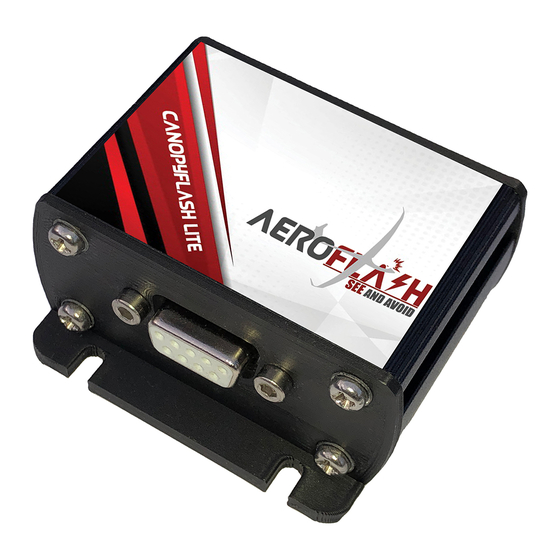
- Page 8 “See and Avoid” starts with being SEEN Rev 3 - AUG 2021 Scope of delivery CanopyFlasher LITE system: 1x PowerBox device. 1x CanopyFlasher with 3M double sided adhesive foam tape pre-applied and cable set***. 1x DB9 - DB9 extension cable (1 meter).
- Page 9 “See and Avoid” starts with being SEEN Rev 3 - AUG 2021 AeroFlash BASIC system: 1x PowerBox PRO device. 1x FuselageFlasher, with 3M double sided adhesive foam tape pre-applied, with 4 meter pre-attached AWG20 wiring (3 wires: red, red, black) - other lengths available on request.
- Page 10 Fuse/circuit breaker, 2A or 3A - available from us separately. Silicone sealant/kit (for weather-proofing the FuselageFlasher). Additional power cable. Crimp or soldering tools. Cable ties, cable clips. Status LEDs The CanopyFlasher LITE features two different colored status LEDs indicating the following: Green status LED: System switched off.
-
Page 11: Power Consumption
PowerBox (PRO) systems accept a power input of 10V to 20V DC. There is NO fuse inside, nor included with the system. Suitable fuses or circuit breakers are available from our dealers, or from AeroFlash directly. PowerBox (PRO) requires a minimum thickness of 20AWG wire (standard... - Page 12 Weight: ±15 grams without cable / ±95 grams with 4m cable. Temperature specifications and cooling requirements All AeroFlash components are designed to operate in temperatures ranging from -30 to +60ºC. These temperature limitations depend on the actual ambient conditions. Generally with high-summer (>30°C) temperatures some precautions must be observed.
- Page 13 3M “Dual Lock” super strong double sided adhesive tape and some cable ties. In any case AeroFlash should be mounted in accordance with the installation requirements as per (a.o.) CS-SC036a and CS-SC402b. The CanopyFlasher comes prepared with super strong black 3M double sided adhesive foam tape.
- Page 14 “See and Avoid” starts with being SEEN Rev 3 - AUG 2021 4. Installation instructions and examples The installation of an AeroFlash system must comply with EASA regulations as per Standard Change CS-SC036a “INSTALLATION OF VISUAL AWARENESS LIGHTS”: click here for the link to the EASA document.
- Page 15 “See and Avoid” starts with being SEEN Rev 3 - AUG 2021 Using the supplied vinyl grid sticker may make it easier to align the CanopyFlasher so it’s perfectly straight. It may be very difficult to see the alignment once you try to stick it to the canopy from the inside.
- Page 16 Now that you have mounted the CanopyFlasher, it’s time to take care of the cable set. The AeroFlash installation consists of commonly seen male and female DB9 (D SUB 9) type connectors for the data cables (status LEDs and temperature sensor), and for the power supply of the CanopyFlasher. It is sturdy, easy to attach, separate, and highly suited for the currents.
- Page 17 “See and Avoid” starts with being SEEN Rev 3 - AUG 2021 Wire color Wire description Flasher +9-20V VCC/Positive (internally connected with pin 6) YELLOW Temperature sensor +5V WHITE Temperature sensor signal BLUE Common signal GND (ISOLATE FROM PIN 9!)
- Page 18 “See and Avoid” starts with being SEEN Rev 3 - AUG 2021 Side-opening canopy installations - general Each glider type requires a specially designed connector solution. This is unique to every different glider type. A brief installation instruction manual...
- Page 19 “See and Avoid” starts with being SEEN Rev 3 - AUG 2021 Side-opening canopy installations - Schempp-Hirth This section mostly applies (but is not limited to, or possible for all) to Schempp-Hirth gliders. For example Cirrus gliders require a vertical-opening canopy connector solution.
- Page 20 “See and Avoid” starts with being SEEN Rev 3 - AUG 2021 Find a suitable place to install the 7-pin CanopyConnector that is attached to the CanopyFlasher. You need to install this CanopyConnector to the canopy frame using one of the supplied mountings at a location where when the canopy is closed, it can make good contact with the opposite part.
- Page 21 “See and Avoid” starts with being SEEN Rev 3 - AUG 2021 Step 1 Depending on your glider type, we included a suitable angled mounting support in order for you to optimally mount it in your specific glider. It may be required to...
- Page 22 “See and Avoid” starts with being SEEN Rev 3 - AUG 2021 Step 2 To find the proper mounting position for the connector on top of the mounting support, it’s recommended to use some simple double-sided adhesive tape to try various positions.
- Page 23 “See and Avoid” starts with being SEEN Rev 3 - AUG 2021 Step 3 Included with the kit is a simple plastic drilling template to resemble the PanelContact. It comes pre-applied with some general purpose double sided adhesive tape. On the other side are two slightly oversized pins that clamp into the alignment holes in the CanopyConnector.
- Page 24 “See and Avoid” starts with being SEEN Rev 3 - AUG 2021 washer underneath the head of the bolt; only between the instrument panel cover and the locking nut. Do not over-tighten the bolts. It’s better to leave a tiny bit of play between the connector and the instrument panel cover, so that the alignment is easier.
- Page 25 “See and Avoid” starts with being SEEN Rev 3 - AUG 2021 trailer fuselage support can damage it. Ensure that the selected location is also accessible from the inside of the fuselage. Observe the roundness of the fuselage: The FuselageFlasher has a 1,6mm...
- Page 26 “See and Avoid” starts with being SEEN Rev 3 - AUG 2021 Step 4 FuselageFlasher is completely waterproof. We do however strongly recommend to seal the edge of the flasher and fuselage with a bit of white silicone kit. This will prevent dirt and water from coming underneath the flasher, which may affect the adhesive tape.
- Page 27 +11* to 20V INPUT (VCC, positive) (AWG20) *FuselageFlasher may not work optimally at voltages below 11V. It is not advisable to use weaker lead-acid batteries with AeroFlash FuselageFlasher. Installation of the OFF/ON switch A drill hole of 6mm is required for the OFF/ON switch.
- Page 28 “See and Avoid” starts with being SEEN Rev 3 - AUG 2021 Post-installation system check After installation, please double-check if you correctly wired everything up. The system is not protected from reverse polarisation! Check if the OFF/ON switch and label is correctly orientated on the instrument panel and only hand-tighten the nut.
- Page 29 “See and Avoid” starts with being SEEN Rev 3 - AUG 2021 7. Appendix AeroFlash product comparison Nexus Nexus Fusion Fusion Fusion Fusion Fusion Fusion Power Power MINI (Nexus) LITE FLARM (Nexus) LITE FLARM Flarm compatible RJ12 IGC ports...
Need help?
Do you have a question about the CanopyFlasher LITE and is the answer not in the manual?
Questions and answers