
Summary of Contents for SKIOLD UNI-MIX 1000 GM: 590061
- Page 1 SKIOLD A/S REV. 2 /08.11.2011 Kjeldgaardsvej 3 DK-9300 Sæby CE/ab Denmark 70016GB Tel.: +45 99 89 88 87 Fax: +45 99 89 88 77 skiold@skiold.com www.skiold.com INSTRUCTION MANUAL SKIOLD UNI-MIX 1000 GM TYPE NO. 590061...
-
Page 2: Table Of Contents
1.0 TABLE OF CONTENTS 1.0 TABLE OF CONTENTS ................2 2.0 FIGURES ....................2 3.0 WARNING .................... 3 4.0 FUNCTION DESCRIPTION ............... 4 5.0 MOUNTING ..................5 5.1 Erection Tools ................. 5 5.2 Instructions for Erection ..............5 5.3 Mounting of Motor and Gear ............. 5 5.4 Erection of the Mixer ............... -
Page 3: Warning
3.0 WARNING At service, inside cleaning, or if for some reason it is necessary to stay in the mixer, the current must be disconnected at the main panel, and the switch must be secured with a lock. If emptying takes place directly from the outlet of the mixer or the emptying auger to the floor or into open trolley, for safety reasons a pipe of minimum length 850 mm must be mounted on the outlet. -
Page 4: Function Description
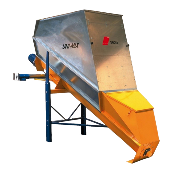
4.0 FUNCTION DESCRIPTION Fig. 1 Mixing principle Pos. 1 Motor Pos. 2 Gear Pos. 3 Mixer auger Pos. 4 Inspection/cleaning door Pos. 5 Inlet door Pos. 6 Auger trough Pos. 7 Superstructure The mixer consists of an inclined auger trough, pos. 6, in which the mixer auger, pos. -
Page 5: Mounting
5.0 MOUNTING 5.1 Erection Tools Hand hammer Screwdrivers with straight and star slot Ring/fork wrench 8, 10, 13, 17 and 19 mm Various allen keys Tackle, min. allowed load 500 kg Ladder 5.2 Instructions for Erection The mixer must be erected on an even, concreted floor with a bearing capacity of min. - Page 6 Fig. 3 Mounting flange for motor The motor is fastened with the enclosed 4 pcs. M12x30 bolts with belonging discs. Fig. 4 Mounting of motor on gear - 6 -...
- Page 7 Remove the plug for oil filling at the top of the gear and replace it with an air- escape valve. Fig. 5 Air-escape valve for gear Grease the hollow shaft of the gear in order to ease the mounting on the mixer auger.
-
Page 8: Erection Of The Mixer
5.4 Erection of the Mixer The auger trough is mounted with auger and hopper with safety grid when supplied from the factory. In order to secure that the mixer is tight attach the enclosed tightening tape to all assembled surfaces before the mixer superstructure is mounted. The pos. -
Page 9: Mounting Of Emptying Auger
Fig. 7 Erection of the mixer 29 12 13 30 31 5.5 Mounting of Emptying Auger Fig. 8 Mounting of emptying auger Pos. 1 Auger trough Pos. 2 Q20 clamp Pos. 3 Ø 102 mm single or double auger outlet Single emptying auger can be mounted to the right or to the left. -
Page 10: Addition Of Liquids
5.6 Addition of Liquids Fig. 9 Example of addition of liquids Pos. 1 Piping for liquids from pump Pos. 2 Flexible connection for weighing system Pos. 3 Drip stop (excess-pressure valve, 1 bar) Pos. 4 Inlet pipe, adjustable in the height It is recommended to add the liquids approx. -
Page 11: Mounting Of Ventilator
5.7 Mounting of Ventilator Fig. 10 Mounting of ventilator Place filter and ventilator cornerwise in two separate corners of the cover as shown in figure 10. It is of no importance which side of the mixer is chosen. - 11 -... -
Page 12: Mounting Of Load Cells
5.8 Mounting of Load Cells The load cells are normally supplied on foot. DO NOT fasten the foot to the floor, as the load cells must be able to centre themselves during loading. If the load cells are fixed, faulty load may occur causing faulty weighing. Mount a swivel pin with conical nut on each load cell. - Page 13 If you weigh into the mixer from auger, mill with cyclone or the like – and it is the case of a closed system – you must use flexible connctions between the transport system and the weighing system, figure 12 pos. 3. Fig.
-
Page 14: Starting The Mixer
6.0 STARTING THE MIXER Check that there are no foreign bodies in the mixer before start-up. Check that the direction of rotation is correct. The mixer auger shall take the material towards the outlet. If an emptying auger is removing the mixed material from the mixer, you adapt the capacity adjusting the outlet throttle of the mixer. -
Page 15: Operation
7.2 Operation In order to obtain the best utilization of the mixer, the following should be followed: - Various components to be mixed can be added manually via the hopper or automatic with an auger, fan, pump or the like. - If the mixer is equipped with emptying auger, so that the outlet throttle is always totally or partly open, a small portion will be left in the outlet and this portion will not be mixed with the rest. -
Page 16: Maintenance
- After the mixing the mixer is emptied via outlet, emptying auger or fan depending on the construction of the plant. During emptying the mixer must be in operation in order to empty the mixer completely. - NB: The emptying capacity must be adapted to the capacity of the transport auger by adjusting the throttle in the mixer outlet. -
Page 17: Fault Finding
Depending of the humidity of the grain, grinding method and quantity of liquids added the mixer auger and inner surfaces may be covered by dirt. This may build fertile soil for poisonous fungus and germs, so that the mixer must be regularly cleaned inside. -
Page 18: Technical Specifications
11.0 TECHNICAL SPECIFICATIONS Fig. 15 Dimensional sketch 2050 3775 1130 Technical data: Mixer volume 2800 l Mixer capacity: - Dry feed max. 1000 kg - Moist feed from moisture-proof silo max. 800 kg - Dry feed with fat/oil max. 1000 kg - Dry feed with molasses max. -
Page 19: Ex-Zone Specification
12.0 EX-ZONE SPECIFICATION Fig. 16 Ex-zones Zone 22 Zone 21 Ex-zones according to unified standards DS/EN 1127-1, DS/EN 50281-3, DS/EN 13463-1. Around the mixer and in a distance of min. 1 m to the extreme point is zone 22. Inside the mixer is zone 21. In order to observe above zones the mixer must be equipped with cover, and the inspection and filling doors must be closed while the mixer is in operation, or the mixer is filled by the mechanical feeding system. -
Page 20: Accessories
13.0 ACCESSORIES Cover 590021 Inlet connection Ø 150 200010G Inlet connection Ø 150, 60° 590026 Flexible connection Ø 150 1920399 Ventilator with filter 590024 Emptying auger, Ø 102 single, 1.1 kW 280 rpm 590093 Emptying auger, Ø 102 single, 1.1 kW 560 rpm 590094 Emptying auger, Ø... -
Page 21: Spare Parts List
14.0 SPARE PARTS LIST Pos. Code No. Description Wearing part 591026 Mixer auger 6407077 Bearing (2) 6801007 Gear, I = 34.91 2320093 Motor 4 kW 1400 rpm, B5, IEC112 Fig. 17 Spare parts - 21 -... -
Page 22: Ce/Atex Declaration Of Conformity
15.0 CE/ATEX DECLARATION OF CONFORMITY CE/ATEX DECLARATION OF CONFORMITY The signer SKIOLD A/S Kjeldgaardsvej, 9300 Sæby, Denmark, tel. No. +45 99 89 88 87 hereby declare that the product: Description Type UNI-MIX 1000 GM with motor 590061 was constructed and manufactured in conformity with...
Need help?
Do you have a question about the UNI-MIX 1000 GM: 590061 and is the answer not in the manual?
Questions and answers