Table of Contents
Advertisement
Quick Links
Advertisement
Table of Contents

Summary of Contents for Buggies4One RAMBLA Mk 1
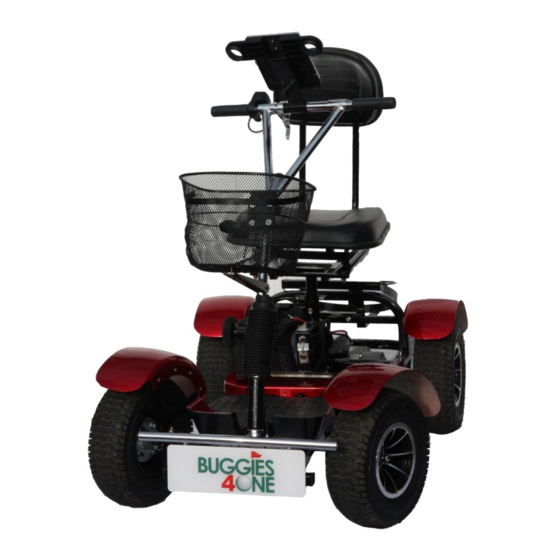
- Page 1 USER MANUAL RAMBLA Mk 1 Page 1...
-
Page 2: Table Of Contents
CONTENTS RECEIVING & CHECKING YOUR BUGGY……………….3 TECHNICAL INFORMATION..……………………………….5 ASSEMBLY (FIRST TIME)..……………………………………8 OPERATING FUNCTIONS…………………………………….11 LOADING & UNLOADING……………………………………15 DRIVING SAFELY………………………………………………...16 MAINTENANCE…………………………………………………..17 TROUBLE SHOOTING………………………………………….19 YOUR BUGGY DETAILS……………………………………….21 WARRANTY DETAILS…………………………………………..22 Page 2... -
Page 3: Receiving & Checking Your Buggy
RECEIVING YOUR GOLF BUGGY On receiving your Buggy we suggest the Instruction Manual is read through carefully. The manual provides instruction on how to drive safely, includes technical information, maintenance routines and troubleshooting chart. Please fully check receipt of ALL separate parts. These are as follows: 1. - Page 4 Page 4...
-
Page 5: Technical Information
TECHNICAL INFORMATION Full dimensions (LxHxW) 1510x1093x743mm Folded dimensions (seat & fender removed) 1420x640x743mm Front & Rear Sections separated (minimum) 1050x600x743mm Total weight of Buggy (including battery) 77kg Heaviest individual part (Rear Body) 35kg Maximum carrying capacity 200kg Motor/gearbox output 1000watt Battery 24V…..50ah Battery Weight... - Page 6 EXPLODED VIEW Page 6...
- Page 7 PRIMARY COMPONENT LIST ITEM NO PART NUMBER DESCRIPTION QTY PER BF1-10 MOTOR/GEARBOX ASSEMBLY BF1-71 REAR STABLISER ASSEMBLY BF1-30 TEE HANDLEBAR ASSEMBLY BF1-73 FRONT FENDER BF1-50 FRONT FRAME ASSEMBLY BF1-72 FOOTBOARD MAT BF1-22-02-RED FRONT OFFSIDE MUDGUARD BF1-22-03-RED REAR OFFSIDE MUDGUARD BF1-40 REAR FRAME ASSEMBLY BF1-22-04-RED NEARSIDE FRONT MUDGUARD...
-
Page 8: Assembly (First Time)
ASSEMBLY (FIRST TIME) Your Golf buggy has been assembled, and fully tested prior to despatch. It has arrived part dismantled for boxing and shipment. Assembly is straight forward and can be accomplished with the tools supplied. Remove all parts from the box. Line up Rear and Front body sections and push together until they lock. - Page 9 Fit the Seat Support pillar. Locate the bolt into the centre hole and tighten. Height adjustment up or down can be done later to suit the driver. Make sure the orientation is correct. The seat can be assembled from the front by locating the sliders onto the end of the guide rails.
- Page 10 Note The Lithium battery will come approximately 50% charged. It is recommended prior to the buggy being used that it is fully charged. Install the battery in the nearside compartment and connect the power lead. The power lead can only be inserted when located correctly. Fit the Basket, Golf Bag Holder, Umbrella Holder and Front Fender as required.
-
Page 11: Operating Functions
OPERATING FUNCTIONS KEY SWITCH Controls the power supply from the battery to the Buggy. When turned to the “ON” position the indicator on the handlebar will illuminate. The buggy is ready to operate. Switch FUNCTIO Charge SWITCH Controls power CHARGING PORT supply from the Located underneath the seat is the charging port for the battery. - Page 12 THUMB ACCELERATOR CONTROL Controls forward and reverse motion. With the key switch “ON” the 3 LED indicators light up. These indicate the battery level, with all 3 on the battery is fully charged. With the brake lever in the up position gentle pressure on the accelerator lever will drive the buggy under power.
- Page 13 BRAKE RELEASE LEVER When engaged (Lever in the down position) the buggy is in drive mode. To change to freewheel mode the lever is pushed up. When pushed up the buggy drive is inoperative. Free Wheel Drive HANDLEBAR The handlebar position can be adjusted by loosening the locking nut at the base of the bar.
- Page 14 USB PORT The buggy is fitted with a dual USB charging port for connecting directly into a mobile phone, GPS device or other suitable equipment. POWER SAVE In order to save battery life if the key switch is left “ON” the electrical system after 20 minutes will go to power save.
-
Page 15: Loading & Unloading
LOADING & UNLOADING With many SUV’s and estate cars it is often possible to load the buggy without dismantling the 2 main body frames. The use of suitable loading ramps is recommended. The handlebars can be dropped down, the basket can be removed if necessary together with the front fender, stabilizer wheel and golf bag support. -
Page 16: Driving Safely
DRIVING SAFELY ON THE GOLF COURSE 1. Good practice is to always have the battery fully charged when going out for a round. 2. Check all component parts are in good working order. 3. Make sure the Buggy is assembled correctly. 4. -
Page 17: Maintenance
MAINTENANCE The Buggy in general requires minimal maintenance and relies mostly on good housekeeping to remain in good working condition. Battery The lithium battery requires no maintenance. It is supplied pre-charged but will require a full charge before use. To charge the battery this can be done in situ on the buggy or using the separate charging cable supplied. - Page 18 Controller Located in the box under the seat it requires no maintenance other than checking cable connections look in good condition and are free from dirt and debris. Jack Plug Located underneath the junction between the front and rear body section it can collect dirt and should be wiped clean.
-
Page 19: Troubleshooting
TROUBLESHOOTING No lights on the controller REASON Key Switch is off Turn On Battery is Flat Recharge Battery Jack Plug disconnected Reconnect Battery Lead Disconnected Reconnect Control unit damaged Contact Retailer Lights are lit but Buggy fails to drive. REASON Brake lever in down position Move to up position for drive Possible loose wire in control box... - Page 20 Buggy pulls to one side REASON Unequal tyre pressure Check and reset Steering rods out of alignment or Contact retailer damaged Damaged gearbox Contact retailer Buggy struggles to drive. REASON Low on power Check Battery condition Excessive Weight Reduce weight Tyre pressure low Inflate above 10psi min.
-
Page 21: Your Buggy Details
YOUR BUGGY DETAILS MODEL RAMBLA Mk1 DATE ……………… ORDER No ……………… SERIAL No …………….. MOTOR …………….. HQ-005 CONTROLLER ……………… WARRANTY Your Buggy carries a free 12 month guarantee and a 12 month guarantee on the lithium battery valid from the date of purchase. In the unlikely event of a product failure the Company will repair or replace any faulty products free of charge. -
Page 22: Warranty Details
CONTACTS Customer Services…………….info@buggies4one.com Service & Repair ……………….info@buggies4one.com Tel. +44 (0)1562 519613 www.buggies4one.com Page 22... - Page 23 IM-21-01 Page 23...