
Summary of Contents for Tek Drive TDS-F8
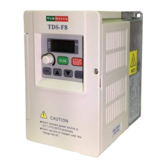
- Page 1 東達變頻器 TDS-F8 簡易說明書 Brief Instruction Manual 小型標準變頻器/ Compact Standard AC Drive 單相 Single phase 110V Class 0.5~ 1HP 單/ 三相 Single/ Three phase 220V Class 0.5~ 2HP 三相 Three phase 440V Class 0.1~ 2HP...
- Page 2 TDS-F8 簡易說明書/ Brief Instruction Manual F8 完整使用說明書下載 (詳細參數說明請參照) Download F8 Instruction Manual for more information *本手冊內容若如有更改,恕不另行通知。 *The content of this manual may be revised without prior notice. 東達科技股份有限公司 TEK-DRIVE CO., LTD. TEL: (02)2275-6859 FAX: (02)2275-6867 Email: service@tekdrive.com.tw http://www.tekdrive.com.tw 202104...
- Page 3 以便獲 得更詳細的說明。 Thank you for using TDS-F8 Compact Standard Inverter (drive, VFD) developed by TEK-DRIVE Co., Ltd., featuring High-Performance and ultra-low noise. In the course of using, in case of any problems not covered by this Manual, please contact local agents or engineering technical personnel from our company.
- Page 4 ➢ 若變頻器安裝於控制盤內時,務必加裝散熱風扇,使變頻器周溫 低於 45℃。 ➢ 在未將馬達連接線從變頻器的輸出端子 U、V 及 W 分離前,不 可對馬達線執行高阻抗絕緣測試。 警告 ➢ 不可對變頻器內部零組件作耐壓測試。 ➢ A VFD or VFDs installed in an enclosure, be sure the installation location for cooling effect, and use an external cooling fan or air condition in a suitable location to maintain the internal temperature of enclosure as45 Max..
-
Page 5: Table Of Contents
目 錄/ Content (See Page 5) 1. TDS-F8 使用說明 1-1 收貨檢查-----------------------------------------------------------------------------------------6 1-2 安裝方向與空間-------------------------------------------------------------------------------7 1-3 安裝環境注意事項----------------------------------------------------------------------------7 1-4 儲存注意事項----------------------------------------------------------------------------------7 1-5 TDS-F8 標準規格-------------------------------------------------------------------------------8 1-6 外型尺寸---------------------------------------------------------------------------------------10 1-7 基本配線---------------------------------------------------------------------------------------11 1-8 端子配置與說明------------------------------------------------------------------------------12 2. 變頻器周邊設備注意事項 2-1 周邊設備配線注意事項--------------------------------------------------------------------14 2-2 主回路配線用器具及注意事項-----------------------------------------------------------15 2-3 系統配置圖例---------------------------------------------------------------------------------16 3. 變頻器的操作說明 3-1 操作器顯示部與 LED 指示燈-------------------------------------------------------------17 3-2 按鍵機能與顯示項目說明-----------------------------------------------------------------18... - Page 6 5. 故障顯示及排除 5-1 異常故障發生原因及排除方法-----------------------------------------------------------31 5-2 警告顯示及排除方法------------------------------------------------------------------------32 6. 附錄 6-1 外加剎車電阻選用表------------------------------------------------------------------------34 6-2 交流輸入電抗器選用表---------------------------------------------------------------------34 6-3 輸入雜訊濾波器選用表---------------------------------------------------------------------34 6-4 RFI 零相濾波器--------------------------------------------------------------------------------35 6-5 數位操作器安裝尺寸------------------------------------------------------------------------36...
- Page 7 1. TDS-F8 Introduction 1-1 Preliminary Inspection------------------------------------------------------------------------------------39 1-2 Mounting & Installation-----------------------------------------------------------------------------------40 1-3 Installing Location Condition Free----------------------------------------------------------------------40 1-4 Storage Condition------------------------------------------------------------------------------------------40 1-5 TDS-F8 General Specification---------------------------------------------------------------------------41 1-6 Frame Size & Dimension---------------------------------------------------------------------------------43 1-7 Wiring & Connection--------------------------------------------------------------------------------------44 1-8 Terminal Configuration and Description----------------------------------------------------------------45 2. Precautions for F8 Peripheral Equipment...
-
Page 8: Tds-F8 使用說明
1. TDS-F8 使用說明 1-1 收貨檢查 每部變頻器在出廠前,均經過嚴格的品管,客戶變頻器拆箱後,請執行下列檢查步驟: ⚫ 檢查變頻器銘板上機種型號是否與外箱登錄相符。(請參閱銘板標示) ⚫ 檢查變頻器是否有因運輸過程中造成損傷。 ◼ 變頻器銘板標示: ◼ 變頻器型號說明 TDS - F8 - L 0P4 E 3 位置號碼: 位置 位置 名 稱 說 明 名 稱 說 明 號碼 號碼 產品名稱 TDS: 變頻器產品 E: 標準... -
Page 9: 安裝方向與空間
1-2 安裝方向與空間 為確保 TDS-F8 變頻器之散熱,請依下圖 1-1 之安裝空間設置: (a)左右空間 (b)上下空間 圖 1-1 TDS-F8 安裝空間圖 1-3 安裝環境注意事項 安裝環境對變頻器的功能發揮及其使用壽命會有直接的影響,因此安裝 TDS-F8 變頻器, 必需考慮下列因素: ⚫ 周圍溫度:-10℃ ~ +45 ℃ ⚫ 防止雨水、濕氣或直接日曬。 ⚫ 防止腐蝕性液體或氣體、塵埃及金屬細屑。 ⚫ 防止振動或電磁干擾之場所。 ⚫ 若多台變頻器同時安裝於同一控制盤內時,請加散熱風扇,使變頻器周溫低於 45℃。 1-4 儲存注意事項 ⚫ 必須置放無塵垢、乾燥之位置 ⚫ 儲存位置的環境溫度必須介於-20℃ ~ +60℃以內。... -
Page 10: Tds-F8 標準規格
1-5 TDS-F8 標準規格 ◼ F8-標準型規格 單相 110V 輸入電壓等級 單/ 三相 220V 三相 440V 機種型式 F8-****E(3) N0P4 N0P7 L0P4 L0P7 L1P5 H0P7 H1P5 最大適用馬達 0.75 0.75 0.75 額定輸出容量(kVA) 額定輸出電流(A) 輸 出 三相 200 ~ 230V 三相 380 ~ 460V 最大輸出電壓(V) 可由參數設定 (最高可達 400Hz) 最高輸出頻率(Hz) - Page 11 機種型式 F8-****E(3) N0P4 N0P7 L0P4 L0P7 L1P5 H0P7 H1P5 冷卻方式 自然冷卻 強制 自然 強制風冷 重量 (kg) 使用場所 室內(無腐蝕性氣體塵埃等之場所) 環 -10 ~ +45℃(不結凍狀態) 周圍溫度 境 -20 ~ +60℃ 保存溫度 規 90%RH 以下(不結露狀況) 濕度 格 海拔 1000 米以下,5.9m/s (0.6G)以下 (JISC0911 基準) 標高、振動 Modbus RS-485 標準內建...
-
Page 12: 外型尺寸
1-6 外型尺寸 圖 1-2 TDS-F8 尺寸圖 安裝尺寸 (mm) 外型尺寸 (mm) 適用馬達容量 概略重 入力電壓 KW/ HP 量(kg) 0.4KW/ 0.5HP 1Ø 110V 0.75KW/ 1HP 0.4KW/ 0.5HP 1Ø/ 3 Ø 0.75KW/ 1HP 220V 1.5KW/ 2HP 0.75KW/ 1HP 3 Ø 440V 1.5KW/ 2HP... -
Page 13: 基本配線
1-7 基本配線 圖 1-3 變頻器標準配線圖 ( ◎表示主回路端子,○表示控制端子 ) -
Page 14: 端子配置與說明
1-8 端子配置與說明 ◼ 主迴路端子說明 端子記號 端子內容說明 R/L1 S/L2 主回路輸入電源 (單相輸入,只接 R - S) T/L3 P/B1 P/B1 - B2: 外接剎車電阻 (恆壓專用機無、110V 機種為訂製) U/T1 V/T2 變頻器輸出,連接三相馬達 W/T3 接地端子 (第三種接地) ◼ 主迴路端子配置 220V 0.5~2HP/ 440V 1~2HP 三相機種 110V 0.5~1HP/ 220V 0.5~2HP 單相機種... - Page 15 ◼ 控制迴路端子說明 圖 1-4 控制端子配置圖 端子代號 端子功能說明 電氣規格 正轉運轉─停止命令 逆轉運轉─停止命令 多機能輸入端子: 每一個輸入端子 最大 Sink 電流為 三線式操作,Local/Remote 控制,異常復歸,多段速切 換,加減速切換,加減速禁止,外部遮斷,過熱預告,PID 控制,速度尋找,UP/DOWN 機能,外部異常,Timer 機能等 訊號共同點 +15V 速度設定用電源 +15V/ 20mA max. 電壓/ 電流主速指令(0-10V/ 4-20mA) 0~10V/ 4~20mA 多機能類比輸出端子: 0~10V 頻率指令,輸出頻率,輸出電流,輸出電壓,直流電壓, PID 控制量,外部類比指令輸入 AIN 量 輸出指示: 電驛...
-
Page 16: 變頻器周邊設備注意事項
2. 變頻器周邊設備注意事項 2-1 周邊設備配線注意事項 1、 配線時,請根據手冊中的注意事項以及請依照電工法規定施行配線,以策安全。 2、 確定電源電壓及可供應之最大電流。 3、 變頻器出力側端子 U,V,W 絕不可接至 AC 電源側。 4、 主回路端子的螺絲請確實鎖緊,以防止因震動鬆脫產生火花。 5、 交流輸入電源與主回路端子(三相 R/ S/ T,單相 R/ S)之間的連線一定要接一個無熔絲開關。 最好能另串接一電磁接觸器 (MC) 以在變頻器保護功能動作時可同時切斷電源。( 電磁接觸 器的線圈兩端需加裝 R-C 突波吸收器 )。 6、 輸入電源 R,S,T 並無相序分別,可任意連接使用。 7、 主回路配線與控制回路的配線必需分離,以防止發生誤動作。如必需交錯,請作成 90 度的 交叉。 8、... -
Page 17: 主回路配線用器具及注意事項
20、 參數(1-02)出廠設定:當設為 3、5、7(二線式端子)或 4、6、8(三線式端子)時,除(1-01)外,所 有參數設定值均會復歸為出廠初始設定值。若 TDS-F8 原先操作在三線式端子(即參數(1- 02)=4、6、8),改為二線式操作(即參數(1-02)=3、5、7)時,馬達可能會馬上以反方向運轉, 所以要先確認端子 1 及 2 均為“開路”的狀態,以免造成機器或人員之損傷。 21、配線時,請選用適當的電線線徑,當主回路配線很長時,要考慮電壓降不可大於額定電壓之 2%。相間電壓降△V= ×電線電阻 (Ω/km) ×配線距離(m) ×流過電流(A) ×10 。 22、當變頻器與馬達間配線很長時,請適度調降載波頻率( 參數 2-06 )。 2-2 主回路配線用器具及注意事項 交流電源與變頻器的電源輸入端 R/L1、S/L2 間,必須要裝無熔絲斷路器(NFB),而電磁接觸 器(MCB)則視需要決定是否安裝。若加裝漏電斷路器以作漏電故障保護時,為防止漏電斷路器誤 動作,選擇其感度電流為 200mA 以上,動作時間為 0.1 秒以上者。 表 2-1:主回路配線用器具 電纜線(mm 型號... -
Page 18: 系統配置圖例
防止高頻誤動作。 ■ 電磁接觸器(MC) 一般使用時,可以不加電磁接觸器,但要作外部順序控制或停電後自動再起動等功能時,需加裝 電磁接觸器。 請儘量避免使用電磁接觸器作變頻器之運轉/停止控制。 ■ AC 電抗器 若欲作進一步改善功因或抑制外來電源突波時,可外加 AC 電抗器。 ■ 輸入側雜訊濾波器 TDS-F8 搭配專用濾波器,方可符合 EN55011A 級規範 輸入側雜訊濾波器之選用,請參照本使用說明書附錄選用表 ■ 變頻器 輸入側 R, S, (T) 無相序區分,可任意變換,且接地端子 請確實作好接地處理。 ■ 輸出側雜訊濾波器 變頻器輸出側加裝專用雜訊濾波器時,可降低輻射干擾及感應雜訊。 請自行選購輸出側雜訊濾波器,或參照附錄之零相雜訊濾波器之使用說明 ■ 三相感應馬達... -
Page 19: 變頻器的操作說明
3. 變頻器的操作說明 3-1 操作器顯示部與 LED 指示燈 數位操作器有「DRIVE」及「PRGM」兩種操作模式,只有在變頻器停止時,才可以按 鍵來切換 DRIVE 模式及 PRGM 模式。在 DRIVE 模式下,變頻器才可做運轉操作,只有在 PRGM 模式下,才可更改變頻器控制及系統參數內容。 TDS-F8 數位操作器有兩種: 一體式數位操作器:位於變頻器中央位置,可分為按鍵區和顯示區兩部分。按鍵區:為使 用者控制變頻器操作介面;顯示區:提供顯示運轉狀態與參數設定規劃模式;請參考下方 圖 3-1 外接式數位操作器(TMCA-V8 LED):提供數位操作器外拉功能,其為另購配件。當使用外 接式數位操作器時,變頻器操作控制權自動移轉至外接式數位操作器,而一體式數位操作 器只能監視變頻器運轉狀態,無法設定參數及運轉操作。 LED 數位操作器之顯示及按鍵機能如下: 圖 3-1 一體式數位操作器... -
Page 20: 按鍵機能與顯示項目說明
3-2 按鍵機能與顯示項目說明 操作鍵 文章中使用名稱 機能說明 用於循環變換顯示變頻器各項狀態資訊,如頻率指令 功能、顯示鍵 、輸出頻率、輸出電流及參數群。 UP 鍵 參數、數值設定變更時用。(遞增) (+鍵) DOWN 鍵 參數、數值設定變更時用。(遞減) (-鍵) 資料確認鍵 選取參數群組或某一參數名稱(EDIT 機能)、參數設定值 (編輯/輸入鍵) (EDIT 機能)及參數設定完成時(ENTER 機能),按此鍵 RUN 鍵 以數位操作器運轉時,在驅動(DRIVE)模式下按此鍵,變頻 (運轉鍵) 器開始運轉,同時 RUN LED 燈亮*。 以數位操作器運轉時,在驅動(DRIVE)模式下按此鍵,變頻 器停止,同時 STOP LED 燈亮。 STOP/ 故障 以外部控制(參數 2-01 設定為 1 或 2)運轉時,可利用參數 RESET 鍵... - Page 21 ■ 顯示項目說明 操作器顯示項目 機能說明 顯示變頻器目前的設定頻率。 顯示變頻器實際輸出到馬達的頻率。 顯示變頻器輸出側 U、V 及 W 的輸出電流 顯示監視項目。 顯示正轉運行命令。 顯示逆轉運行命令。 顯示參數群名稱 顯示參數群下各項參數項目。 顯示參數項目之內容值。 若由顯示區讀到 End 的訊息(如左圖所示)大約一秒鐘,表示資料已被接受 並自動存入內部記憶體。 若設定的資料不被接受或數值超出時即會顯示。 其餘警告及故障顯示項目,請參考第五章故障顯示及排除。...
-
Page 22: 操作器操作、顯示模式說明
3-3 操作器操作、顯示模式說明 ■ 一體式操作器 TDS-F8 變頻器內含一體式的數位操作器外,其操作方式分別說明如下: (A) 一體式操作器操作顯示模式... - Page 23 ■ 外接式數位操作器 TDS-F8 變頻器除了內含一體式數位操作器外,當使用者需延長外接式數位操作器時,可使用 代號 TMCA-V8 LED 或 TMCA-V803 LED 數位操作器,以 V803 LED 為例,其操作方式分別說明 如下: (B) 外接式數位操作器顯示模式 *1:電源投入後,即進入驅動 (DRIVE) 模式 (操作器 DRV 燈亮),在變頻器停止的狀態下按 鍵,即進入參數編輯 (PRGM)模式 (操作器 DRV 燈熄滅),才可設定參數;需再按 鍵才能回復為 DRIVE) 模式,變頻器方可執行運轉。 *2:在 DRV 的模式下進入參數群時,只能監看、顯示參數,無法改變參數的設定值;此時如需 鍵,即進入參數編輯 (PRGM)模式。 設定參數則請先停止變頻器再按...
-
Page 24: 變頻器參數列表
0 :用戶參數 6 :保護參數 1 :基本參數 7 :電機參數` 2 :操作方式參數 8 :特殊參數 3 :數位、類比輸出端子功能參數 9 :通訊參數 4 :數位、類比輸入端子功能參數 U :監視參數(只可監看不可設定) 5 :多段速以及自動程序運轉參數 本說明書為簡易說明書,僅對參數做重點式的列表說明,如需更詳細的參數說明,請上東達官 網 https://www.tekdrive.com.tw/,下載TDS-F8 使用說明書 ,即有完整的參數說明與解釋 參數一覽表 表格內*1 表示隨機種而定,*2 表示440V級為220V級的2倍,*3 為外接鍵盤,(☆)為運轉中 可設定 0- 用戶參數 參數代號 參數功能 設定範圍 出廠值 設定值... -
Page 25: 2-操縱方式參數
最大輸出頻率 (Hz) 50.0~400.0 60.0 1-03 最大電壓 (V) 0.1~255.0 220.0(*2) 1-04 最大電壓之頻率 (Hz) 0.1~400.0 60.0 1-05 中間輸出頻率 (Hz) 0.1~400.0 1-06 中間輸出頻率之電壓 (V) 0.1~255.0 1-07 最低輸出頻率 (Hz) 0.1~400.0 1-08 最低輸出頻率之電壓 (V) 0.1~255.0 1-09 頻率指令上限 0~109% 100% 1-10 頻率指令下限 0~109% 0% 1-11 加速時間1 0.0~999.9s 10.0s(☆) 1-12... -
Page 26: 3-數位、類比輸出端子功能參數
操作器輸出頻率 UP/DOWN 功能: 0- UP/DOWN 改變頻率後,必須按 鍵 2-08 1- UP/DOWN直接改變頻率,不須按 鍵 3- 數位、類比輸出端子功能參數 參數代號 參數功能 設定範圍 出廠值 設定值 00-頻率指令 06-類比指令 AIN 01-輸出頻率 08-操作器旋鈕 多機能類比 02-輸出電流 09-PID 輸入 輸出 FM 3-01 03-輸出電壓 10-PID 輸出 1 機能選擇 04-直流電壓. 11-PID 輸出 2 05-輸出功率 07/ 12-保留... -
Page 27: 4-數位、類比輸入端子功能參數
4- 數位、類比輸入端子功能參數 參數代號 參數功能 設定範圍 出廠值 設定值 0.0~1000 類比頻率指令AIN增益 (%) 100.0(☆) 4-01 (1000.0 類比頻率指令AIN偏壓 (%) -99.9~100.0 0.0(☆) 4-02 類比輸入頻率指令來源選擇: 4-03 0-電壓訊號 0~10V 1-電流訊號 4~20mA 類比主速頻率指令輸入特性選擇: 0-0~100%(正特性) 2- -100%~+100%(正逆特性) 4-04 1-100~0%(逆特性) 端子 MI2 端子 MI2/ MI3/ MI4/ MI5 機能選擇 4-05 機能選擇 設定值需符合... - Page 28 頻率指令 4 0.0~400.0Hz 0.0Hz(☆) 5-04 頻率指令 5 0.0~400.0Hz 0.0Hz(☆) 5-05 頻率指令 6 0.0~400.0Hz 0.0Hz(☆) 5-06 頻率指令 7 0.0~400.0Hz 0.0Hz(☆) 5-07 頻率指令 8 0.0~400.0Hz 0.0Hz(☆) 5-08 自動程序運轉模式選擇: 0-自動程序運轉模式機能無效 1-執行單一週期之自動程序運轉模式,停止後會由停止前的速 度起,繼續運轉 2-連續循環週期之自動程序運轉模式,停止後會由停止前的速 度起,繼續運轉 3-單一週期結束後,以最後運轉速度運轉,停止後會由停止前 5-09 的速度開始運轉 4-執行單一週期之自動程序運轉模式,停止後會由第一段速度 起,繼續運轉 5-連續循環週期之自動程序運轉模式,停止後會由第一段速度 起,繼續運轉 6-單一週期結束後,以最後運轉速度運轉,停止後會由第一段 速度開始運轉 0- 停止...
-
Page 29: 6-保護參數
6- 保護參數 參數代號 參數功能 設定範圍 出廠值 設定值 加速中失速防止機能選擇 0- 無效 6-01 1- 有效 減速中失速防止機能選擇 6-02 運轉中失速防止機能選擇 6-03 加速中,失速防止動作準位 30~150% 6-04 運轉中,失速防止動作準位 6-05 過轉矩檢出準位 (%) 30~150 6-06 過轉矩檢出時間 (Sec.) 0.0~25.5 6-07 過轉矩檢出選擇: 0- 過轉矩檢出無效 1- 頻率一致時方檢出,然後繼續運轉 6-08 2- 頻率一致時方檢出,然後停止 3- 運轉中檢出,然後繼續運轉 4- 運轉中檢出,然後停止運轉... -
Page 30: 9-通訊參數
瞬停再起動運轉選擇: 8-05 0-無效 1-有效 速度尋找電流準位 (%) 0~150 8-06 速度尋找減速時間 (Sec.) 0.1~25.5 8-07 最小遮斷時間 (Sec.) 0.5~5.0 8-08 頻率跳躍1 (Hz) 0.0~400.0 8-09 頻率跳躍2 (Hz) 0.0~400.0 8-10 頻率跳躍3 (Hz) 0.0~400.0 8-11 頻率跳躍範圍 (Hz) 0.0~25.5 8-12 異常再起動次數 0~10 8-13 計時機能ON延遲時間 (Sec.) 0.0~999.9 0.0(☆) 8-14 計時機能OFF延遲時間... -
Page 31: U-監控參數
U- 監視參數 參數代號 參數功能名稱 單位 頻率指令 0.1Hz 顯示頻率指令,顯示單位可由0-01設定 U-01 輸出頻率 0.1Hz 顯示輸出頻率,顯示單位由0-01設定 U-02 輸出電流 0.1A 顯示變頻器輸出電流 U-03 輸出電壓 顯示變頻器輸出電壓 U-04 主回路直流電壓 顯示變頻器內部的主回路直流電壓 U-05 輸出功率 顯示變頻器輸出功率 U-06 輸入端子狀態 U-07 輸出端子狀態 U-08 變頻器有電壓輸出之時間累積。累積時間範圍 運轉累積時間 0~65535 Hr (小時)。超過65535 Hr後,重新由0開 U-09 始累積。 變頻器輸入側電源投入到電源OFF的時間累積。累積 送電累積時間 時間範圍0~65535 Hr。超過65535 Hr後,重新由0 U-10 開始累積。... - Page 32 異常發生時的頻率指令 0.1Hz U-19 異常發生時的輸出頻率 0.1Hz U-20 異常發生時的輸出電流 0.1A U-21 異常發生時的輸出電壓 顯示的內容,用以記錄最近一次異常發生時 U-22 之變頻器運轉狀況,表示狀態同上。 異常發生時的直流電壓 U-23 異常發生時的運轉累積時間 U-24 異常發生時的輸入端子狀態 U-25 異常發生時的輸出端子狀態 U-26 異常履歷 1 U-27 最近一次發生的異常內容 異常履歷 2 U-28 前一次發生的異常內容 異常履歷 3 U-29 前二次發生的異常內容 異常履歷 4 U-30 前三次發生的異常內容 EPROM軟體編號 出廠軟體編號,廠商用以追查軟體版本。 U-31 顯示...
-
Page 33: 故障顯示及排除
5. 故障顯示及排除 變頻器具有警告及保護功能。一旦警告機能動作時,數位操作器上會顯示警告內容,此時 異常接點輸出端子並不動作。當異常故障發生時,保護功能動作,變頻器停止輸出,馬達自由 運轉停止,數位操作器會顯示異常原因,同時異常接點輸出端子動作。 5-1 異常故障發生原因及排除方法 異常故障 故障現象說明 異常發生原因 排除方法 顯示內容 運轉中,主回路直 1. 電源系統容量不足,電壓壓降 1. 檢查輸入電源電壓是否正常 流電壓太低 太大 直流電壓 2. 檢查電源容量是否太小 過低 2. 電源側電磁接觸器不良 變頻器輸出電流大 1. 變頻器輸出端短路或接地 1. 檢查輸出端配線是否正確 於變頻器額定電流 2. 馬達容量遠大於變頻器容量 2. 檢查馬達與變頻器容量是否匹 2 倍 配 過電流 3. 變頻器與馬達間接線鬆動 3. -
Page 34: 警告顯示及排除方法
異常故障 故障現象說明 異常發生原因 排除方法 顯示內容 變頻器輸出端接地 馬達絕緣不良 1. 檢查馬達繞線阻抗是否匹配, 且接地電流高於變 是否漏電 輸出端接線不良 地短路 頻 器 額 定 電 流 的 2. 檢查輸出端配線 50%以上 RS-485 通訊異常檢 1. RS-485 通訊參數設定不當 檢查 RS-485 通訊參數設定 出,且設定為停止 2. RS-485 接線不當 檢查 RS-485 接線 RS-485 運轉方式 3. - Page 35 警告顯示 警告現象說明 發生原因 排除方法 正/反轉指令同時投 運轉程序設計不當 1. 檢查系統回路配線 (閃爍) 入時間超過 500ms 。 2. 檢查運轉程序設計 (變頻器依 2-03 所設 指令輸入 定的方式停止) 不正確 1. 注意 220V/440V 級的不同,設 參數設定範圍不良 1. 變頻器容量設定(1-01)不當 定適合的 KVA 數 參數輸入 2. 參數設定超過設定範圍 不正確 2. 重新執行參數復歸( 1-02 ) 1. 4-05~4-08 的設定值,不滿足 4- 1.
-
Page 36: 外加剎車電阻選用表
6.附錄 6-1 外加剎車電阻選用表 最大適用馬達 外加剎車電阻等效規格 輸入電壓 概略剎車轉矩 ( 10% ED) 等級 Ω 160%↑ 160%↑ 0.75 162% 0.75 126% 119% 6-2 交流輸入電抗器選用表 輸入電壓 最大適用馬達 額定電流值 電感值 等級 相數 3Ø 3Ø 0.75 3Ø 3Ø 0.75 3Ø 6-3 輸入雜訊濾波器選用表 輸入電壓 最大適用馬達 標準型濾波器 額定電流值 A 等級... -
Page 37: Rfi 零相濾波器
6-4 RFI 零相濾波器 請參考下表,東達科技提供三種不同的 RFI 零相濾波器,請自行根據應用的差異來選擇適合的 濾波器。 外型尺寸 (mm) 型號 FC-80D*50d*20H FC-63D*38d*12H 圖 6-2 零相濾波器環 圖 6-1 FC-ZF-46 (含固定座) ❖ 安裝例 DRIVE REM OTE DRIVE REM OTE DIGITAL OPERAT OR JN EP- 31 DIGITAL OPERAT OR JN EP- 31 PRGM PRGM DSPL DSPL... - Page 38 ❖ 衰減特性...
-
Page 39: 數位操作器安裝尺寸
6-5 數位操作器安裝尺寸 ◼ TMCA-V8 LED... - Page 40 ◼ TMCA-V803 LED 操作器與外拉固定框尺寸 ❖ TMCA-V803 LED ❖ 外拉固定框 75 4 . 21 5 . 71 4 .
-
Page 41: Tds-F8 Introduction
1. TDS-F8 Introduction 1-1 Preliminary Inspection ◼ Receiving After unpacking the TDS-F8: ⚫ Verify that the part/ type code numbers on the drive nameplate match the numbers on your purchase order or packing slip. ⚫ Check the unit for physical damage which may have occurred during shipping. If any part of the drive is missing or damaged, notify the carrier and your TEK-DRIVE Representative immediately. -
Page 42: Mounting & Installation
1-2 Mounting & Installation Do enhance the operation reliability and life time of F8, the F8 should be installed in an environment for temperature increase free, such as in an enclosure or box. Fig. 1.1 shows the minimum free space required around the F8 to guarantee adequate cooling. (a) Free space Front View (b) Free space side view Fig. -
Page 43: Tds-F8 General Specification
1-5 TDS-F8 General Specification ◼ F8 Specification 3Ø 440V Voltage in Class 1Ø 110V 1 / 3Ø 220V N0P4 N0P7 L0P4 L0P7 L1P5 H0P7 H1P5 Type F8-****E(3) Applicable Motor 0.75 0.75 0.75 Output Rating (kVA) Output Current (A) 3Ø 380 ~ 460V Max. - Page 44 N0P4 N0P7 L0P4 L0P7 L1P5 H0P7 H1P5 Type F8-****E(3) IP00, IP20 (Optional) Protective Class Natural Fan Cooling Natural Cooling Cooling Method Cooling Cooling Approximate Weight (kg) Application Site Indoor (No Corrosive Gas, Dust, etc.) Nominal Ambient Operating -10 ~ +45℃(Non-Frozen) Temperature -20 ~ +60℃...
-
Page 45: Frame Size & Dimension
1-6 Frame Size & Dimension Fig. 1.2 TDS-F8 Dimension Mounting Size Appearance Size Approx. Applicable Motor (mm) (mm) Power Supply Weight KW/ HP (kg) 0.4KW/ 0.5HP Single-Phase 110V 0.75KW/ 1HP 0.4KW/ 0.5HP Single-Phase/ 3-Phases 0.75KW/ 1HP 220V 1.5KW/ 2HP 0.75KW/ 1HP... -
Page 46: Wiring & Connection
1-7 Wiring & Connection Fig. 1.3 F8 Standard Connection Diagram ( ◎Mains Circuit Terminals, ○Control Circuit Terminals ) -
Page 47: Terminal Configuration And Description
1-8 Terminal Configuration and Description ◼ Main Circuit Terminals Description Symbol Terminal Description R/L1 Main Power Input S/L2 (R/L1 – S/L2 for Single-Phase Input) T/L3 For extended Braking Resister connection. P/B1 (P/B1 – B2 for Standard Type F8 Only, 220V & 440V models built-in, 110V model is optional by order) U/T1 V/T2... - Page 48 ◼ Control Circuit Terminals Description Fig. 1.4 Control Circuit Terminals Configuration Signal Level Terminal Description Forward Run/ Stop (2-wire configuration) Reverse Run/ Stop (2-wire configuration) Fault Reset Input Photo-coupler Insulated Multi-function Sequence Inputs SINK Signal Input, 6mA/ Multi-Step Reference 1 (DIns) each Multi-Step Reference 2...
-
Page 49: Precautions For F8 Peripheral Equipment
2. Precautions for F8 Peripheral Equipment 2-1 Precautions for Wiring of Peripheral Equipment 21、Please follow the Safety Instruction and National/ Local Electrical Standard when make the wiring for F8. 22、Make sure the Mains Power must be able to carry the F8’s Load Current and Voltage. 23、Never connect the F8 output terminals U/T1, V/T2 and W/T3 directly to the AC Mains Power. - Page 50 39、The semiconductor components are susceptible to high voltage, it is not allowed to carry out voltage tests (Megger) on the internal components of VFD. 40、Observe proper electrostatic discharge procedures (ESD) when handling the drive and circuit boards. Failure to comply may result in ESD damage to the drive circuitry. 41、All parameters value (except parameter 1-01) will be set back to their original value when parameter (1-02) Initialize parameter value is set to 3、5、7 (2-wire Initialization) or 4、6、8 (3-wire Initialization).
-
Page 51: Main Circuit Wiring, Peripheral Equipment And Note
2-2 Main Circuit Wiring, Peripheral Equipment and Note Be su re to connect MCCB or fuses between the AC main circuit power supply and VFD input terminals R/L1, S/L2 (& T/L3) to protect the input wiring, whether a MC needs to be installed depends on the situation. Where a residual current device (RCD) is used for protection in case of direct or indirect contact, only a Type B RCD is allowed on the supply side of this product. -
Page 52: Connecting Peripheral Equipment
Installation of a reactor is effective for improvement of power factor on the power supply side. ◼ Input Noise Filter In order to confirm to EMC Standard EN55011A, please installs a TDS-F8 dedicated filter. Please refer to the Chap. 6 Appendix of this manual to select a correct input noise filter. ◼... - Page 53 Install a noise filter on the VFD’s output side to reduce the radio noise & inductive noise. Please buy an output side noise filter by yourself, or you can refer to the description of Chap.6-4 RFI Noise Filter. ◼...
-
Page 54: Operating Via The Operator (Keypad)
Only in the PRGM mode, user can change the control and system parameters of F8. TDS-F8 has two types of digital operator: Local Operator (LOP): located in the center of F8, it consists the LED indicators, display area and function keys. -
Page 55: Function Key Instruction
3-2 Function Key Instruction FUN. Key Title Function Description Used to display various status information cyclically of F8, such as Function/ frequency command, output frequency, output current and parameter Display Key group. UP Key Increment key for function, parameter or set value. (+... - Page 56 ◼ Display Section Description Displayed Meaning & Description Display frequency reference set value. Display output frequency value. Display output current value. Monitoring item. Motor is rotating in FWD command. Motor is rotating in REV command. Parameter group “0” Parameter number “2” of group 0. Value of this parameter.
-
Page 57: Menu Structure For Operators
3-3 Menu Structure for Operators ◼ Local Operator (LOP) Fig. 3.3 LOP Screen Structure... - Page 58 External Remote Operator (ROP) In addition to the LOP in the TDS-F8, user needs to extend the operator for remote controlling at some application, they can use the code TMCA-V8 LED or TMCA-V803 LED digital operator. Takes V803 LED as an example, the operating methods are described as follows.
-
Page 59: Parameter List & Introduction
This manual is a brief manual, just only make a simple list and description for the parameters. If you need more detailed parameter description, please go to the TEK-DRIVE official website: https://www.tekdrive.com.tw/, to download the TDS-F8 Instruction Manual, there are complete parameter descriptions and explanations in it. Parameter List Sometimes, there is a mark as following in the table, *1 means the value will be different as different F8 type. -
Page 60: 2- Operating Method Parameters (Run Command And Frequency Reference Source)
Middle Output Frequency (Hz) 0.1~ 400.0 1-06 Voltage at Middle Output Frequency (V) 0.1~ 255.0 1-07 Minimum Output Frequency (Hz) 0.1~ 400.0 1-08 Voltage at Minimum Output Frequency (V) 0.1~ 255.0 1-09 Frequency Reference Upper Limit 0~ 109% 100%* 1-10 Frequency Reference Lower Limit 0~ 109%... -
Page 61: 3- Digital & Analog Output Terminal Parameters
3- Digital & Analog Output Terminal Parameters Parameter Name & Description Setting Range Default User set 00- Frequency Reference 06- Terminal AIN 01- Output Frequency 08- OP-POT Terminal FM 02- Output A. 09- PID Input Analog Output 3-01 03- Output V. 10- PID Output 1 Selection 04- DC Bus V. -
Page 62: 5- Multi-Preset Reference & Auto Operation Parameters
00- REV of 3 wires CTL 14- PID disable Multi- 01- Run Command by OP 15- PID (I) Reset 4-05 function Input 02- Run Command by TMN 16- OH pre-alarm MI2 Selection 03- Fault Reset 17- External Fault (N.O.) 04- Multi-step SPD 1 18- External Fault (N.C.) Multi- 05- Multi-step SPD 2... -
Page 63: 6- Protection Parameters
5-13 Process Operating Mode Selection 4 5-14 Process Operating Mode Selection 5 5-15 Process Operating Mode Selection 6 5-16 Process Operating Mode Selection 7 5-17 Process Operating Mode Selection 8 0.0~ 6000 5-18 Process Operating Time 1 0.0(☆) (6000.0 ) (Sec.) 5-19 Process Operating Time 2 0.0(☆) -
Page 64: 7- Motor Data Parameters
7- Motor Data Parameters Parameter Name & Description Setting Range Default User set Motor Rated Current (*.*A) *.*A 7-01 Motor No-load Current (%) 0~ 99 7-02 Motor Rated Slip (%) 0~ 9.9 7-03 Auto Torque Compensation Gain 0.0~ 2.0 7-04 8- Special Parameters Parameter Name &... -
Page 65: 9- Rs-485 Modbus Communication Parameters
9- RS-485 Modbus Communication Parameters Parameter Name & Description Setting Range Default User set Station Address (ID#) 01~ 255 9-01 Modbus Communication Baud Rate (bps): 0-1200 2-4800 4-19200 9-02 1-2400 3-9600 5-38400 Modbus Communication Parity Selection: bit must be “2”) 0*- No Parity 1- Even Parity 2- Odd Parity... - Page 66 Fault Record 2 Most Recent Fault Record U-28 Fault Record 3 Most Recent Fault Record U-29 U-30 Fault Record 4 Most Recent Fault Record EPROM Code F8 firmware version U-31 TEK-DRIVE VFD Model means TDS-F8 model VFD U-32 U-33 Reserved...
-
Page 67: Warning/ Fault Condition, The Possible Cause And Remedies
5. Warning/ Fault Condition, the possible Causes and Remedies F8 has built-in the warning and fault protective functions. When the F8 detects a fault, the fault message is displayed on the operator and activates a fault signal output, after which the motor coasts to a stop. Unlike faults, warning do not activate fault contact outputs. -
Page 68: Warning Condition (Message Flashes), The Possible Causes And Remedial Actions
Fault Name and Possible Causes Remedies Condition There has been F8 output exceeded the F8 - Check on mechanical overload on motor or the machinery (bearing, gearbox, chains, belts, etc.). Overtorque Protection Detect level. - Reduce the load. - Larger than 6-06. Overtorque - Check on acceleration, deceleration, cycle Time. - Page 69 Fault Name and Possible Causes Remedies Condition - See Remedies for fault oL3 of 5-1 Fault There has been F8 output exceeded the F8 Condition…. Overtorque Protection Detect level. - Larger than 6-06. Overtorque - And longer than 6-07. - And set 6-08= 1 ro3 (keep running after detected). RS-485 Modbus Communication Error and keep - See Remedies for fault CErr of 5-1 Fault Condition….
-
Page 70: Appendix
6. Appendix 6-1 Dynamic Braking Resister Input Voltage Applicable Motor Equivalent SPECs of Additional BKR Rough BR Torque Class Ω ( 10% ED) 160%↑ 0.75 160%↑ 162% 0.75 126% 119% 6-2 Input AC Reactor Input Voltage Applicable Motor Rated Current Inductance Class Phases... - Page 71 Fig. 6.2 FC-ZF-46 (mounting base included) ❖ Installation Example DRIVE REM OTE DRIVE REM OTE DIGITAL OPERAT OR JN EP- 31 DIGITAL OPERAT OR JN EP- 31 PRGM PRGM DSPL DSPL DRIVE DRIVE EDIT EDIT ENTER ENTER RESET RESET STOP STOP When install the zero-phase core, no matter it is installed on the input or output side of the inverter, the three wires (R, S, T or U, V, W) must run through the same zero-phase core together and be wound in the same...
-
Page 72: Mounting Dimension Of External Remote Operator
6-5 Mounting Dimension of External Remote Operator ◼ TMCA-V8 LED Dimension... - Page 73 ◼ TMCA-V803 LED Dimension and Mounting Kit ❖ TMCA-V803 LED Dimension ❖ Mounting Kit 75 4 . 21 5 . 71 4 .
-
Page 74: Abbreviation Index
6-6 Abbreviation Index In this manual, there are Abbreviation with Uppercase Words because of limited space in some tables, please refer the following explanation to know what the real meaning of the word. Alphard Abbreviation Meaning Acceleration, Accelerating, Accelerative Auto Process Operation Auto Voltage Regulation B.B.
Need help?
Do you have a question about the TDS-F8 and is the answer not in the manual?
Questions and answers