Table of Contents
Advertisement
Quick Links
Advertisement
Table of Contents

Related Manuals for Meditech C-Scan


Summary of Contents for Meditech C-Scan
- Page 1 Digital Portable Diagnostic Ultrasound System User's Manual Ver. 1.2-49 PLEASE READ ALL OF THE INFORMATION IN THE PACKAGE INSERT BEFORE USING THE SPIROMETER. IF YOU DO NOT UNDERSTAND THE INSTRUCTIONS, CONSULT MEDITECH, service@meditech.cn Meditech Equipment co., Ltd.
- Page 2 Please place the manual in an easily accessible location. Product name:Digital Portable Diagnostic Ultrasound System Product Model:C-Scan Version:E01...
- Page 3 Product manual: A. The system will fully apply quantitative analysis tools which have only been used in research laboratories before into routine clinical examination, so that users can extract more critical diagnostic information through cardiovascular image. B. The system uses real, raw data DICOM networking capabilities, enabling users to fully manage data, which can exchange a variety of medical findings, and these data will be open for future quantitative analysis.
- Page 4 Advice: In order to ensure the safe use of this equipment, please comply with the following requirements: A. Only qualified medical personnel with a professional qualification certificate can use this system. B. Only qualified acoustic images can be used for medical scans for the purpose of medical diagnosis.
- Page 5 They should be recycled or discarded according to local laws and regulations, and classified according to environmental protection requirements properly. Meditech shall be responsible for the performance, reliability and safety of the instrument only if all of the following requirements are met: If it does not comply, it is not within the scope of the Company's responsibility: A.
- Page 6 The company owns the copyright of this non-public publication manual and reserves the right to treat it as confidential information. D. Meditech Equipment co., Ltd. has the right of final interpretation of this manual. Issued Date: Warranty and maintenance services The warranty period of the purchased product shall be subject to the sales contract.
- Page 7 After the expiration of warranty, we can continue to provide maintenance services at your own costs. If you are unable to pay the fees for the charged repair service in time, we may suspend the service until we receive your payment. After - sales service units service@meditech.cn...
- Page 8 User Manual framework(Including three parts) Safety Specifications Volume: Describes patient safety and operator safety information, and points out the system's compliance standards and safety regulations. User Manual Main Volume: Describes the system operating procedures, maintenance checks, basic functions, system daily preparation work and instructions for using the system.
-
Page 9: Table Of Contents
ONTENTS Safety Specifications Volume ................1 Chapter 1 Safety Specifications .................. 1 The text used in this manual ..................... 3 A description of the safety symbol and the device label ..........4 Identify the label ........................5 Safety classification ......................6 Patient safety ........................ - Page 10 Transport equipment ......................31 Chapter 6 Basic Screen Layout and Menus .............. 32 System Setup Area ........................32 Parameter control area ......................32 Parameter display area ....................32 Image scanning area ......................32 Parameter control area ....................33 Teaching display area ...................... 33 System Setup Area......................
- Page 11 10.4 Video storage ........................54 10.5 End the examination......................55 10.6 Patient Archive ........................56 10.7 Image Measure and Play ....................59 Probe and consumable operation volumes ............62 Chapter 11 System Maintenance and Care .............. 62 11.1 System maintenance ......................62 11.2 Use of the probe .......................
-
Page 12: Safety Specifications Volume
Chapter 1 Safety Specifications This chapter describes important safety measures to be taken before operating the C-SCAN system, and also points out the system's compliance criteria. To ensure the safety of the patient and the operator, please read the following safety regulations before using the unit. - Page 13 spark generated by equipment failure or the fan motor may electronically detonate these substances. Do not place the probe in a chemical (e.g. corrosive, degradable, contaminated) environment to avoid damage to the device / probe due to strong acid or alkali. Operators should pay attention to the following points to avoid the risk of such explosion:...
-
Page 14: The Text Used In This Manual
occur, causing a short circuit hazard. Be sure to use the power adapter supplied with this unit. If the unit malfunctions, please contact your sales office or agent of UTI Technologies. Do not dispose of this product yourself. 1.1 The text used in this manual Indicates a particularly hazardous situation which, if not avoided, could result in: Severe or fatal injury... -
Page 15: A Description Of The Safety Symbol And The Device Label
Indicates a potential non-compliance situation that could result if unavoidable: Abnormal wear and tear of equipment Invalid operation 1.2 A description of the safety symbol and the device label Description symbol This symbol indicates "power on" This symbol indicates "Power Off". This symbol indicates "equipotential". -
Page 16: Identify The Label
Ambient temperature, transport and storage Ambient temperature range 5 ° C to 40 ° C (non-condensing). 1.3 Identify the label Digital Portable Diagnostic Ultrasound System MODEL:C-SCAN INPUT: AC 100V-240V 50Hz POWER CONSUMPTION: DC3.8V 2500mAH Probe: The orange ring indicates a convex array probe and the green one indicates a linear array probe. -
Page 17: Safety Classification
If the probe parameters or specifications change, consult your local authorized representative or refer to the latest instructions. 1.4 Safety classification In accordance with the degree of anti-electric shock: Application components for the B-type applications. According to the degree of protection against harmful liquid into: Host: IPX0 (general equipment);... - Page 18 Do not use the system in the presence of flammable gas (such as anesthetic gas, hydrogen) or flammable liquid (such as ethanol, etc.), otherwise it may cause an explosion. Connect the power adapter to a dedicated ground socket on the hospital ...
-
Page 19: Operator Safety
temperature and inspection mode. To avoid burns, do not expose the probe to the same part of the patient's body for extended periods of time. In the conditions to meet the diagnosis, try to shorten the inspection time. Diagnostic scan is not allowed during device charging. ... -
Page 20: Safety Of The Probe
During operation, avoid long periods of repetitive operations, regular breaks to relax the muscles. Do not force the probe too hard to avoid the operation in an uncomfortable posture caused by the operator hand, wrist or arm fatigue. 1.7 Safety of the Probe If the probe falls or collides with the object, do not use the probe until the ... -
Page 21: Electrical Safety
Never disinfect the probe with steam, heating or liquid sterilization methods, which will cause permanent damage to the probe. Do not connect or disconnect the probe during real-time scanning; the system must be in freeze mode or the system is switched off before connecting or disconnecting the probe. -
Page 22: Emc
the equipment complying with EN 60601-1. If the equipment is connected with the equipment complying with other relevant national standards, the whole system should meet the requirements of EN 60601-1. The components of this equipment and all accessories at the end of their ... - Page 23 Use a different power supply than the affected equipment to supply the equipment. Consult the authorized representative for additional recommendations. The manufacturer is not responsible for any interference or reaction caused by the use of an interconnected cable other than the recommended cable, or unauthorized alteration or modification of the equipment.
- Page 24 manufacturer does not bear this risk. The product should not be used in close proximity to, or stacked with, other equipment. If it must be used close or stacked, verify that it is functioning properly in its intended configuration. This product declaration meets the requirements in Table 1-Table 3 Table 1 Guidance and manufacturer's declaration - electromagnetic emission The equipment is intended to be used in the electromagnetic environment specified below, and the...
- Page 25 Transient Burst ±1 kV On the input and should have the quality that IEC 61000-4-4 output lines is used in a typical commercial or hospital environment The network power supply should have the quality that surge ±1 kV Line to line is used in a typical IEC 61000-4-5 ±2 kV Line to ground...
- Page 26 conduction 150 kHz~80 MHz values) corresponding to the frequency of the IEC 61000-4-6 3 V/m transmitter. Radio frequency 80 MHz~2.5 GHz 3 V/m Recommended isolation distance radiation d=1.2 IEC 61000-4-3 d=1.2 80 MHz~800 MHz d=2.3 800 MHz~2.5 GHz 式中: P — — Maximum transmitter output power, in watts (W), provided by the transmitter manufacturer;...
-
Page 27: Alara Principle (As Low As Reasonably Achievable)
150 KHz~80 MHz 80 MHz~800 MHz 800 MHz~2.5 GHz d=1.2 d=1.2 d=2.3 0.01 0.12 0.12 0.23 0.38 0.38 0.73 For transmitters maximum ratings not listed above, the recommended separation distance, d, in meters (m), can be determined using the formula in the corresponding transmitter frequency column, where P is the transmitter provided by the transmitter manufacturer The maximum rated output power in Watts (W). -
Page 28: Safety Statements
1.11 Safety Statements Although it has been shown that there is no harmful biological effect of the ultrasonic frequency, intensity, and radiation time used during the inspection using this system, we recommend the use of the lowest acoustic output setting in order to produce satisfactory diagnostic information. -
Page 29: User's Manual Main Volume
The number of elements of the C5-2 probe is 128 elements, the center frequency is 3.5MHz, the radius of curvature is 60mm, scanning mode is electronic convex array scanning. 2.1.1 Specification of product specification and its division Model:C-SCAN Model Description C-SCAN Product subclass code: L-linear array/ C-convex array... -
Page 30: Performance
E.g. C-SCANL means Digital Portable Diagnostic Ultrasound System with L-linear array 2.1.2 Performance Device specifications Volume:165.3 x 85.4 x 19.8 mm Probe length:1150 mm Weight:L:550g/C:570g Display size:6 inch LCD Power specifications Power supply:DC3.8V,2500mA Lithium battery capacity:5400mAh ... - Page 31 Maximum detection ≥160 ≥50 depth (mm) Lateral ≤3(depth≤80) ≤2(depth≤40) resolution ≤4(80<depth≤130) (mm) Axial ≤2(depth≤80) ≤1(depth≤50) resolution ≤3(80<depth≤130) (mm) Blind spot ≤5 ≤3 (mm) Slice thickness ≤8 ≤5 (mm) Horizontal geometric ≤15 ≤10 position accuracy (%) Vertical geometric ≤10 ≤5 position accuracy (%) Area measurement...
- Page 32 Working Storage Conditions Working environment Ambient temperature:5℃~40℃ Relative humidity:30%~75%(No condensation) Atmospheric pressure:700hPa~1060hPa Storage environment Ambient temperature:-10℃~55℃; Relative humidity:30%~95%(No condensation) Atmospheric pressure:700hPa~1060hPa Functional requirements Touch screen: capacitive touch screen control Imaging mode: B mode and C mode ...
-
Page 33: Intended Use
Patient Information: Patient name Gender ID number Medical history Application scenario: General, maternity Measurement information: Length Area Arrow Angle Perimeter Text Transmission system: WLAN transmission Internal storage Battery life requirements Charging time: not more than 5 hours (charging adapter output: DC5V / ... -
Page 34: Contraindications
screening, field rescue. Note: Do not use for fetal gender discrimination. 2.3 Contraindications Do not apply to the eye. 2.4 Target population Target population: Adults, adolescents, pregnant women and fetuses (not used for fetal sex examination). 2.5 Lifetime This product is designed to be used for a period of five years. -
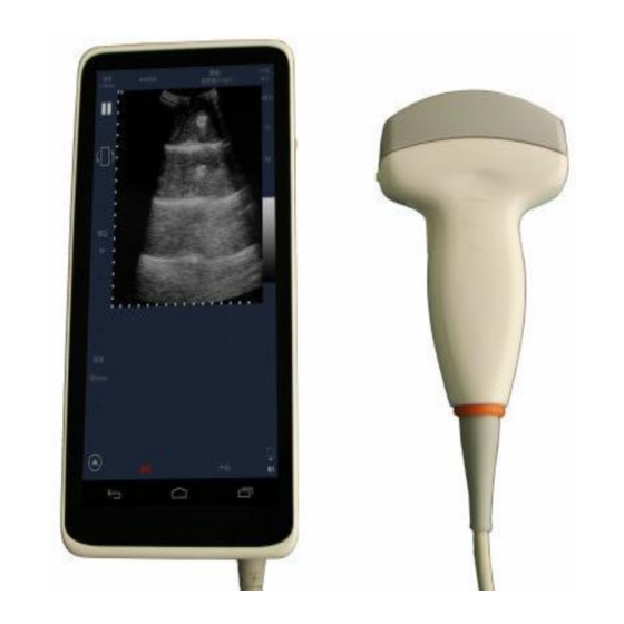
Page 35: Chapter 3 System Appearance
Chapter 3 System Appearance 3.1 System Appearance Note: Volume button: Control the gain of main interface of scanning, that is, volume "+" is increased, the volume "-" is reduced. Freeze / Start button:Control the freeze / start of the scanning;press the freeze/start button once can freeze the current scanning interface, press the freeze/start button again can start scanning;... -
Page 36: Introduction To Parts
The probe Probes are purchased in a medical device production qualification and registration certificate of the manufacturers, each C-SCAN system contain a linear/ convex array probe. Charging interface The charging interface is located below the system, and the USB port ... -
Page 37: Chapter 4 Operation Panel Function Introduction
Chapter 4 Operation Panel Function Introduction icon name function Description The initialization Initialize the system to scan Power on the display Freeze key Freeze the scanned image The current state is the state of the scan Thaw key Resume the scanned image The current state is frozen Flip left / right of the current The red dot on the left indicates the... - Page 38 Batch processing Batch processing of saved Can be deleted, save, compare and keys images other operations Sort key Storage sort method The default mode and sort by time Overlay list can be selected Show hidden keys Overwrite Shows or hides to show or hide Emergency key emergency help...
-
Page 39: Chapter 5 Storage And Transportation Of The System
Chapter 5 Storage and Transportation of the System Do not turn ON the unit's power switch until all system connections and installation preparations have been completed. 5.1 Environment requirement If you use a device that emits radio waves around your device, this device may malfunction. -
Page 40: Power Requirements
Operating the equipment in the wrong voltage range will cause equipment damage, we are not responsible for warranty maintenance caused by such situations. To ensure stable operation of the instrument, the C-SCAN system should use a standard adapter, ensuring that the power supply system is working properly. -
Page 41: Mobile Devices
the general means of transport, but should prevent severe shock and vibration in the transport, and should be moisture-proof, rain-proof measures. Storage Packaged digital portable diagnostic ultrasound system should be stored in a room that meets the conditions in the table below and in a well-ventilated room. Storage conditions -10℃-55℃... -
Page 42: Transport Equipment
5.5 Transport equipment Before transporting, make sure the equipment is ready. Shipping equipment steps: Disconnect charged connections and place them in the box. Park the vehicle on a flat surface to facilitate loading and unloading. Secure the unit so that it does not shake. Place a pad underneath the ... -
Page 43: Chapter 6 Basic Screen Layout And Menus
Chapter 6 Basic Screen Layout and Menus The factory default setting linear/Convex array probe B-mode image settings. Boot interface shown below: Parameter display area Image scanning area Parameter control area Teaching display area System status area System Scanning mode choice Setup Area button optimization... -
Page 44: Parameter Control Area
the direction of the probe marks. 6.3 Parameter control area The parameter control area shows the image parameters of the currently active application, including depth, gain, and freeze. 6.4 Teaching display area The teaching display area shows teaching functions in different positions, including physiological anatomy, manipulation practice, and reference for manipulation photos. -
Page 45: One Button Optimization
6.8 One button optimization This button is to calibrate the image effect of black and white to the best condition. Chapter 7 Turning on / off the system 7.1 Check before starting Please check before boot: The probe line is normal. ... -
Page 46: System Settings
If you use the abnormal heat of the probe, that may burn the patient. If any abnormality is found, it indicates that the unit is defective. Please immediately shut down and contact the company's sales offices, customer service or agents. 7.4 System Settings When open the system for the first time, enter into the main interface. - Page 47 Go to "Settings" in WLAN, and search out a series of network, select a network and enter password to connect. After successful connection, the scanning application can consequently be used with WLAN login. Enter "Settings", select "Display", click "screen brightness" to adjust the brightness. Adjusting the contrast and brightness of the display is one of the important factors in obtaining high-quality images.
-
Page 48: Shut Down The System
7.5 Shut down the system Press and hold the shutdown button to turn off the system. When the system displays the shutdown screen, it indicates that the system is turned Before shutdown, it is recommended to freeze the image and save the useful images in case that the data are damaged or lost during the shutdown. -
Page 49: Software Update
again. 7.6 Software Update Enter the main scanning interface and unfold the menu, click about, then click check update, fill in the blanks with your information. The update will be initialized. Chapter 8 Clinical Application Types 8.1 B mode scanning Linear: The system has different scanning scenarios, corresponding to different clinical application types. - Page 50 The number of frames Freeze the image filled with images per second(frames second), also referred to the refresh rate Flip the image probe orientation product name Thermal index Mechanical index number images saved Change Networking connected Mode status and battery icon End button Slide for this area...
- Page 51 In clinical scanning, for different scanning scenarios, the operator only needs to select the marked area on the bottom of the screen, and the corresponding measurement functions are common in different scenarios. Note: Press "probe frequency" can switch different probe frequencies during the scanning. Press the Save icon during the scanning can save the still image of the current frame , the red number on the right side shows the number of saved images, click the number can view the image list,...
- Page 52 The left bottom is the menu button , click to pop-up menu options. 10. Press the bottom of the Small Parts, Muscle, Vascular, Superficial can choose the corresponding measurement mode,the default is “Vascular” mode. "Superficial" mode interface displays in a horizontal screen, and it displays a thumbnail image on the right side, Click to view.
-
Page 53: C Mode Scanning (For Convex And Linear)
8.2 C mode scanning (for convex and linear) Color gain index Pulse repetition frequency Wall filter reflection area of Speed for flow of blood 8.2.1 Note: In the interface of C mode scanning, press to change from C mode(Figure 8.2.1) into B mode(Figure 8.1.1). -
Page 54: Chapter 9 Measurements And Application (For Both Linear And Convex)
Chapter 9 Measurements and application (For both linear and convex) 9.1 General scanning Click the initialization key, the system enters the scanning state, real-time scanning status interface is shown in the left, click the left and right flip key, run the image as shown on the right. -
Page 55: Distance Measurement
9.2 Distance measurement Length measurement: select the "length", the current state is red, the finger touches the screen and trigger a yellow solid dot above the finger, move the finger and the dot will follow until stopping at the specified coordinate point; touch the screen again, another dot will appear and move until stopping at another specified coordinate point to form a measurement line and mark the distance. -
Page 56: Area Measurement
9.4 Area measurement Select the "area", in order to locate the image area, select 3 points to determine an oval area, then the system automatically identifies the area of this selected region. 9.5 Arrow Arrow function: select the "arrow", mark on the image, the first touch designates the location of the arrow and the second operation rotates the arrow to determine the direction of the arrow. -
Page 57: Angle
9.6 Angle Arrow function: Select the "angle", determine the First point location with finger, use finger to determine another point, the two point will be connected with a straight line, then determine the third point with finger, this point will be connected with the first point in another straight line. -
Page 58: Perimeter
9.7 Perimeter Select the "area", in order to locate the image area, select 3 points to determine an oval area, then the system automatically identifies the perimeter of this selected region. 9.8 Text Select the "text", make a point at the scanning interface, it will show an inputting interface. -
Page 59: Imt
9.9 IMT Select the “IMT”,put the cube at the edge of the carotid,it will automatically measure the thickness of intima. -
Page 60: Special
9.10 Special 9.9.1 In the scanning interface menu, click "special" option to enter the 2B mode selection interface (Figure 9.9.1),The default display is None. Click "2BL" option to enter the 2BL interface (Figure 10.9.2);Click the "2BR" option to enter the 2BR interface;Click the "None" option to return to the main interface of scanning. -
Page 61: Biopsy
9.11 Biopsy 9.10.1 In the scanning interface menu, click biopsy to enter into the biopsy options interface (Figure 9.10.1). The default display is none. Click "Degree A"," Degree B" and “Degree C" to select different angles. Click "PICC" to jump to the "Superficial" measurement mode interface.The interface will be transverse. -
Page 62: Chapter 10 Instruction And Storage
Chapter 10 Instruction and Storage 10.1 Patient Information Maintenance Click " Please select a patient" in the upper right corner of the scanning interface to enter the patient information list interface .Click the 'Add' button to enter to edit Patient Detail interface (Figure 10.1.1),Input relevant information of the patient and click the 'Add' button to save the patient information successfully,the added patient is displayed in the patient information list. -
Page 63: Doctor Information Maintenance
interface of scanning, and you can directly to scan for another patient. If you want to modify the information of added patient, click the Edit button to enter the Patient Information Modification interface. You can modify all the information except the ID. -
Page 64: Image Storage
If you need to modify the information, click the edit button to enter to modify doctor information interface, you can modify all information. Click the search button , can search a doctor by key words, click the delete button to clear the contents, and click the arrow button to close the search bar. -
Page 65: Video Storage
Connect the USB wire to export the pics to the computer or other instruments,if you clicked “save as” for storage. The pictures can be automatically exported to the computer or other instruments. you can find the pics in the file: Internal Storage/Meditech. 10.4 Video storage During real-time scanning, the system will automatically perform the latest 128-frame video caching. -
Page 66: End The Examination
The patient and doctor information is required and the diagnostic content is optional. Save:Save the examination results in the local state. Save as:Save in the external storage Meditech content. Abandon:Delete the current scanned image. -
Page 67: Patient Archive
10.6 Patient Archive In the scan interface menu, click the case file option, enter the case file area. This area displays all local and cloud DICOM files. 10.6.1 All scanned images of the same patient are stored in an ID card. ... - Page 68 ;"Send" means uploading the local images to the cloud(optional with extra cost);"Save as" means saving the image in the external storage Meditech content;Click to "Compare" which means selecting two images to compare shown (Figure 10.6.1 ) Image Details: Select a specific image, enter the image area as shown below.
- Page 69 Print: The result will be printed when Meditech is connected with wifi printer. Share: QR code w be produced after clicking Share, use a phone to scan it, you can see the picture scanned by Meditech in the phone.(The QR...
-
Page 70: Image Measure And Play
Meditech is connected with Wifi) 10.7 Image Measure and Play Click the‘ image thumbnail’ on the left side of the image detail interface, enter the image measure and play interface. 10.7.1 10.7.2 Overlay information: In the frozen state, marked "length, area, arrow, angle, perimeter, text", it ... - Page 71 10.7.3 In the frozen state, if there is no mark "Length, Area, Arrow, Angle, Perimeter, Text" and the logos are not saved, there is no overlay information in the image play detail interface after saving the images. Overlay selected button will display on the list, click to enter the overlay ...
- Page 72 Length, Area, Arrow, Angle, Perimeter, Text:Press 'Length, Area, Arrow, Angle, Perimeter, Text' can make a temporary measurement of the image. click the image by one finger can measurement. The local image can be saved by pressing the Save button . The measurement result of the cloud image can not be saved.
-
Page 73: Probe And Consumable Operation Volumes
Probe and consumable operation volumes Chapter 11 System Maintenance and Care 11.1 System maintenance Equipment should not be frequently turn on and turn off. If you need to reboot after power-off, wait 2 to 3 minutes. Please check whether the system is normal frequently if it has been used ... -
Page 74: Use Of The Probe
Battery treatment should be handled by our company, unauthorized treatment is prohibited to avoid environmental impact. Regarding to the safety of the battery, the following acts should be strictly prohibited: Unauthorized removal of the battery The short-circuit of battery positive and negative ... -
Page 75: Put On Probe Protective Cover
Immerse the probe into sterile water for cleaning Sterilization Dry the probe Examination after use Store 11.3 Put on probe protective cover In order to minimize the spread of the disease, it is necessary to take some protective measures. Clinically, the probe sheath is beneficial to prevent infection. It is strongly recommended to use a sterile probe sheath that meets the requirements when performing surgical procedures. -
Page 76: Probe Maintenance
whether the probe sheath is out of date. 11.4 Probe maintenance 11.4.1 Precautions Overview If the probe is stored for a long period of time, follow the storage requirements of the label on the box. After the probe has been stored for a long time, disinfect the probe again. ... -
Page 77: Clean The Probe
required by the manufacturer during the high sterilization period. Should avoid prolonged exposure to the probe in the air and launch sound waves, so as not to damage the probe. Do not try to split the probe. Splitting the probe may cause damage to the ... -
Page 78: Sterilization Of The Probe
When the probe connected to the system, do not clean or disinfect the probe. Do not use gasoline or other organic compound solution to clean the probe. If the probe sticks to body fluids, please disinfect and then clean. ... - Page 79 Sterilization step Sterile gloves must be worn during disinfection / sterilization to avoid infection; The probe must be cleaned before disinfection / sterilization; it is recommended to disinfect / sterilize the probe using the solution in the table below: Operating Chemical Name Reagent name...
-
Page 80: Peripheral Cleaning
Multiple sterilization and sterilization will lead to the decrease of the safety and performance of the probe, so user should minimize the number of disinfection and sterilization. 11.5 Peripheral cleaning Operating Turn off the system, power off the system; ... -
Page 81: Security Inspection
When cleaning the machine, do not let the liquid flow into the machine, otherwise there will be a risk of failure and electric shock. 11.7 SECURITY INSPECTION To ensure that the unit is working properly, it is recommended that a maintenance and inspection plan be established and that the machine be inspected periodically. -
Page 82: List Of Accessories
When the product reaches the service life or needs to be discarded, please contact the customer service department of Meditech Equipment co., Ltd. for recycling. Our company will dispose of the product in accordance with the relevant laws and regulations. -
Page 83: Appendix A Acoustic Output Data
Appendix A Acoustic Output Data A.1 Description Acoustic output The acoustic output display is located at the top right corner of the system display Note: If either MI or TI displays a value greater than 1.0, please follow the ALARA guidelines carefully. The sound intensity parameters usually generated by the ultrasonic probe and their meanings are described as follows: Mechanical index... -
Page 84: A.3Sound Output Report Form
A.3 A.3Sound output report form Linear array Depth mm Convex array depth abdomen Maternity A.4 A.4Sound output of published information Manufacturer:Meditech Equipment co.,Ltd. Electronic Linear array scanning, hand-held 7.5MHz universal probe Electronic convex array scanning, 3.5MHz universal probe mode p/Mpa Ispta/(mW/cm 547.9... -
Page 85: Appendix B Type B Imaging Performance
Output 0dB Lp/mm Wpb6(∥)/mm (⊥)/mm prr/kHz srr/Hz —— Output beam size/mm /MHz 7.58 Maximum power (mW/cm Power on mode B mode Initial mode B mode Acoustic output freeze provide Contact type Include patterns —— 1) sound boot coefficient; 2) sound initial coefficient; 3) power set every 3dB as a level, can be controlled by the user. - Page 86 Frequency range 3.15 ~ 3.85MHz, the sound frequency Sound operating frequency and nominal deviation of the center frequency within ± (MHz) Test frequency ≤2 Lateral resolution (mm) (depth≤40) ≤1 Axial resolution (mm) (depth≤50) Blind spot (mm) ≤3 The maximum depth of detection (mm) ≥50 Geometric Accuracy(%) Horizontal≤10,vertical≤5...
-
Page 87: Appendix C Uses Ultrasound Phantom Illustrations
Geometric Accuracy(%) Horizontal ≤ 15, vertical ≤ 10 Length and area measurement error(%) ±15 Slice thickness (mm) ≤4 Appendix C uses ultrasound phantom illustrations A1---A6: Axis lateral resolution target group B: Blind target group C: Longitudinal target group D: Horizontal target group E: Imitating Tumor F: Imitating gallbladder (diameter:10mm)and stone G: Imitating gallbladder (diameter:6mm) - Page 88 30,50,70,120 and 160mm, the parallel distance of the adjacent target line in A1 and A2 is1,5,4,3,2mm successively, In A3-A6 its 5,4,3,2mm successively, In Longitudinal branch the vertical distance between the center of the adjacent target line is 4,,3,3,1mm respectively. Blind target group: the distance between the center of the adjacent target line are 10mm, distance to the acoustic window are10,9,8,7,6,5,4,3 mm, respectively.
Need help?
Do you have a question about the C-Scan and is the answer not in the manual?
Questions and answers