
Summary of Contents for Okura Robot Palletizer A Series
- Page 1 M933-01 Operation Manual Okura Robot Palletizer Fieldbus Installation OXPA-Qm2 1.0.4.8 -- Rc101.bin 2.02 -- POD (J) 2.02 – POD (E) 1.00G – Okura Yusoki Co., Ltd.
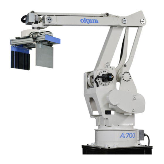
- Page 2 Introduction Thank you for purchasing a model from the Okura Robot Palletizer A series. This manual is a guidebook to help you safely and correctly use your A Series Robot Palletizer. It should be useful not only to beginners who are using an Okura Palletizer for the first time, but also to experienced users, who can use this Manual to reconfirm their knowledge.
-
Page 4: Table Of Contents
Table of Contents 1. OUTLINE 2. PREPARATION 2.1. ABC ································································································· 2-1 2.2. P ABC ········································································· 2-1 OWER ABLE FOR 2.3. S ············································································ 2-1 ETWORK ABLE 2.4. ABC C ···································································· 2-2 ONFIGURATION 2.5. ABC C ····································································· 2-2 ONFIGURATION 2.6. GDS F ····························································································... -
Page 5: Outline
Outline This document explains how to add an optional fieldbus function to a robot controller. The fieldbus function is realized by the addition of an AnyBus Communicator (henceforth, ABC). An additional procedure is shown below. Preparation Preparation required for the addition of ABC Attachment to the robot controller Setup Configuration of ABC... -
Page 7: Preparation
Preparation The fieldbus function in option can be added to the controller. CE and UL controller is already equipped with the DIN rail for attaching ABC. What is required to a fieldbus function is described as follows; 2.1. ABC It is necessary to purchase an ABC to link with Profibus or Ethernet/IP. Profibus AnyBus Communicator-Profibus-DP AB7000... -
Page 8: Abc Configuration Tool
"Configuration Tool for AnyBus Communicator 2.10" can be downloaded from the site of HMS. Configuration Tool is common for all the fieldbuses. http://www.anybus.com/eng/support/support.asp?PID=104&ProductType=AnyBus%20Communicator 2.5. ABC Configuration File Configuration File which Okura Yusoki offers shall be used. You have to download this file to new ABC once. Profibus AbcRc101ProfiDp.cfg Ethernet/IP AbcRc101EhernetIP.cfg... -
Page 9: Setup
Setup 3.1. Configuration ABC Refer to Document of AnyBus Communicator about an setup. Screen 1 ABC and PC are connected by Configuration Cable DC24V supplied to ABC Execution of ABC Config Tool displays [Select Configuration] (Screen 1). A [Cancel] button is clicked and [Select Configuration] is closed COM 1-3 is chosen by /Tools/Port Configuration File is opened by Menu/File/Open [Connect] button of Toolbar is clicked... -
Page 10: Setup Unique To Profibus
3.2. Setup unique to Profibus The switch cover on ABC is opened and Station Address is set up with a rotary switch. 3.3. Setup unique to Ethernet/IP 3.3.1. IP Address IP address is set up using the ping command. Refer to the document of ABC for details. 3.3.2. -
Page 11: Test
Test 4.1. Test of Profibus Starting Profibus Configuration Tool, use your own apparatus master and use ABC for a slave. HMS_1803.gsd is used for registration of Slave. I/O size sets up the same following size as Ethernet/IP. INPUT 52 byte OUTPUT 50 byte The example using SyCon as Profibus Configuration Tool is shown. - Page 12 Input data sent to Profibus from the robot controller and Output data sent to the robot controller from Profibus can be checked. Input data is written by OxpaPlc. This example shows that 1234H has just been written in D2815. Moreover, AA55H is written in D2790 of a data memory from SyCon.
-
Page 13: Test Of Ethernet/Ip
4.2. Test of Ethernet/IP How to test the communication state of the robot controller and Ethernet/IP Scanner with using EIPScan is explained. ABC is turned on ABC and PC are connected by the Ethernet cross-over cable EIPScan is started Menu/Network/Add Device is performed The IP address of ABC is inputted in the [Add New Device] dialog (Screen 5) ABC is displayed on the EIPScan screen (Screen 6) Screen 5... - Page 14 The right click of the [AnyBus-C EtherNet/IP] is carried out, and [Add Connection] is clicked. A type tab is clicked and Target->Originator is set as Point To Point. (Screen 7) Screen 7 Data Size tab is clicked and Data Size of "Originator->Target" and "Target->Originator" is changed into 50 and 52, respectively.
- Page 15 Destination tab is clicked and sets up as Screen 9. Configuration Connection Instance Originator->Target Connection Point Target->Originator Connection Point Screen 9 If it is connected correctly transmitting data and receiving data can be performed. (Screen 10) Blue character Controller->Ethernet/IP Scanner Green character Ethernet/IP Scanner->Controller Screen 10...
- Page 16 The data to the controller from the Ethernet/IP Scanner can be checked by writing a value in a data memory using OxpaPlc. The data written in D2815 appears in blue. The example shows the 1234H is written in D2815. The data from the Ethernet/IP Scanner to the controller clicks the place of a green character, inputting a numerical value is checked by OxpaPlc.
- Page 17 Operation Manual Okura Robot Palletizer Fieldbus Installation 01 Version: 2004.7.31 Okura Yusoki Co., Ltd.
Need help?
Do you have a question about the Robot Palletizer A Series and is the answer not in the manual?
Questions and answers