
Summary of Contents for GENASYS LRAD 500X-RE MMT
- Page 1 LRAD 500X-RE MMT EQUIPMENT MANUAL 500X-RE MMT Catalog: LRAD-500X-RE-MMT-MANUAL Part No.: 116666-00 Rev.07 Aircraft Models: HH-60, UH-1 Revised September 2020 Copyright, 2020, Genasys Inc.
-
Page 2: Table Of Contents
LRAD-500X-RE MMT Table of Contents 1.0 System Description ........................1 1.1 Introduction ......................... 1 1.2 Specifications ........................1 1.3 Functional Block Diagram ..................... 5 1.4 Acoustic Performance ......................6 1.5 LRAD-500X-RE MMT Features ....................9 1.5.1 Mount and Yoke Features ..................... 9 1.5.2 Head Unit Features ..................... -
Page 3: System Description
LRAD-500X-RE MMT 1.0 System Description 1.1 Introduction The LRAD-500X-RE MMT consists of a head unit with four acoustic drivers, helicopter mounting equipment, and a control unit. The control unit includes a built-in digital media (MP3) player and a handheld microphone as well as controls for audio volume, power, voice boost and beam width. - Page 4 LRAD-500X-RE MMT Electrical Normal Power Consumption 60 Watts (Voice content) Peak Power Consumption 265 Watts (Alert tone) Electromagnetic Compatibility FCC Class A radiated and conducted emissions Battery (MFG Part Number: MK Battery ES33-12) Chemistry Sealed Lead-Acid, AGM Capacity 33 Ah Normal Individual Battery Voltage 12 VDC Charger Input...
- Page 5 LRAD-500X-RE MMT Figure 1: Head Unit Dimensions and Hard Mounts Figure 2: LRAD-500X-RE MMT Total System Dimensions – HH-60 Manual Part No.: 116666-00 Rev.07...
- Page 6 LRAD-500X-RE MMT Figure 3: LRAD-500X-RE MMT Total System Dimensions – UH-1 Manual Part No.: 116666-00 Rev.07...
-
Page 7: Functional Block Diagram
LRAD-500X-RE MMT 1.3 Functional Block Diagram Figure 4 shows a block diagram of the major subsystems of the LRAD-500X-RE MMT. The battery box provides power to the DC to DC converter located in the sealed LRAD-500X-RE MMT electronics enclosure. The DC-DC converter accepts 10.5 to 28 VDC on the input and converts it to 48 VDC to drive the 500 W class “D”... -
Page 8: Acoustic Performance
LRAD-500X-RE MMT 1.4 Acoustic Performance The LRAD-500X-RE MMT is capable of projecting extremely loud voice communications or tones towards intended targets. The LRAD’s acoustic output is “focused” in order to achieve maximum sound intensity directly in front of the device. This allows the LRAD-500X-RE MMT to achieve a maximum continuous SPL of 149 dBA at one meter from the front of the LRAD. - Page 9 LRAD-500X-RE MMT The reference SPL and distance for the LRAD-500X-RE MMT is 149 dB at 1 meter at maximum continuous volume. The SPL can be plotted as a function of distance from the LRAD as shown in the following chart: Sound Pressure Level vs.
- Page 10 LRAD-500X-RE MMT LRAD-500X AT 3.0kHz – 5dB PER DIV. Figure 7: LRAD-500X-RE MMT Polar Plot at 3 kHz Table 1: SPL Level Ranges from Polar Plot Angle Range SPL Drop from Polar Actual Max SPL at 1 m Distance to Reach 104 Plots in this Angle Range dBA max in this Angle...
-
Page 11: Lrad-500X-Re Mmt Features
LRAD-500X-RE MMT 1.5 LRAD-500X-RE MMT Features 1.5.1 Mount and Yoke Features This section contains important information on the mount and yoke, which are used to secure and manipulate the LRAD-500X-RE MMT inside of a helicopter. Figure 8: Mount and Yoke - HH-60 (Left) UH-1 (Right) 1. - Page 12 LRAD-500X-RE MMT Figure 9: Mounting Plate - HH-60 (Left) and UH-1 (Right) Disclaimer: Genasys offers mounting plates compatible with the HH-60 and UH-1 helicopter models. It is the customer’s responsibility to verify hole alignment and fit if they intend to install this mount in any similar helicopters.
-
Page 13: Head Unit Features
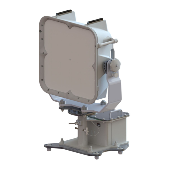
LRAD-500X-RE MMT 1.5.2 Head Unit Features This section contains important information on the head unit, which contains the speakers and power controls for the LRAD-500X-RE MMT. Figure 10: LRAD-500X-RE MMT Head Unit 1. Picatinny Rails • Used to mount accessories, such as a Maxabeam or green laser. 2. - Page 14 LRAD-500X-RE MMT 7. Control Unit Mounting Plate • Allows control unit to be attached to the head unit for local operation of audio controls. 8. Hour Meter • Displays power on hours. 9. Control Unit Input • Connects to the control unit and accepts audio and control signals from the unit. 10.
-
Page 15: Battery Box Features
LRAD-500X-RE MMT 1.5.3 Battery Box Features This section highlights specific features and controls found on the LRAD500X-RE MMT’s battery box. Figure 11: Battery Box 1. Battery Level Gauge • There is a button on the side that, when pressed, will illuminate a set of lights on the front panel indicating battery level (the user should not let the battery level drop below 25%). -
Page 16: Control Unit Features
LRAD-500X-RE MMT 1.6 Control Unit Features The section contains important information on the Control Unit, which has several important features used to operate the LRAD-500X-RE MMT. Figure 12: Control Unit 1. Mic and Audio In, USB Interface • This interface allows for audio input from an external audio source (microphone, CD player, tablet, etc.). - Page 17 LRAD-500X-RE MMT 4. Play/Pause, Stop, Skip Forward, Skip Reverse Buttons • These buttons control playback of MP3 audio files stored on the unit. 5. Backlight Brightness • Cycles button and LCD brightness levels. 6. Repeat Mode • Causes MP3 file to playback in a continuous loop until the user presses the stop button or the LRAD is turned off.
-
Page 18: Recording Microphone Features
LRAD-500X-RE MMT 1.7 Recording Microphone Features The LRAD-500X-RE MMT includes a rugged microphone with an integrated digital recording chip. This microphone can record and store approximately one minute of audio and is also capable of broadcasting live speech. To broadcast live speech, simply press and hold the Push To Talk (PTT) button and speak into the microphone. -
Page 19: Electrical Connections And Signals
LRAD-500X-RE MMT 1.8 Electrical Connections and Signals The following figures show the pin locations and electrical signal designations for the two connectors found on the LRAD-500X-RE MMT: DC Power Input: The DC power input is the main power input connector for the unit. The LRAD-500X-RE MMT can operate at DC input voltage levels between 12 and 28 VDC. -
Page 20: Operating Limits
LRAD-500X-RE MMT • The Control unit is powered by the +12 to 28 VDC on pin 8 of the Control input connector. This voltage is provided by the batteries when the main power switch is in the on position. • When the Power/Volume control on the Control unit is turned on, the unit will supply +10 VDC to the LRAD to turn on the amplifier. -
Page 21: Normal Procedures
LRAD-500X-RE MMT The operation zones in Figure 17 represents safety zones for the LRAD-500X-RE MMT in an open-air environment. The LRAD should be used outdoors in as open of an area as possible. Avoid aiming the LRAD device towards areas where personnel or reflective surfaces such as walls or overhangs may be present. -
Page 22: Control Unit Setup
LRAD-500X-RE MMT 3. Control Unit Mounting Bracket • This attaches to the back of the LRAD-500X-RE MMT to mount the Control Unit. 4. Control Unit 5. Battery Box and Mounting Plate • This includes the 12-jaw cargo fittings. 6. Yoke Safety Bar •... -
Page 23: Battery Charging And Status
LRAD-500X-RE MMT 3.3 Battery Charging and Status Figure 20: MMT Battery Charge Indicator The battery charge indicator, located on the battery box, has 4 graduations for charge level (25%, 50%, 75% and 100%). To test the charge of the unit, press the button labeled “Test Battery Charge.”... -
Page 24: Aircraft Cabin Loading And Unloading
LRAD-500X-RE MMT 3.4 Aircraft Cabin Loading and Unloading Figure 22: Transporting LRAD-500X Above is an example of flight line transport. The LRAD-500X-RE MMT arrives in two pieces: (1) the yoke and head unit and (2) the mounting plate and battery box. CAUTION Use caution while loading and unloading both pieces. - Page 25 LRAD-500X-RE MMT Figure 24: Placing Mounting Plate Figure 23: Placing Mounting Plate and Battery Box into Aircraft and Battery Box into Aircraft (BACK) (FRONT) The above figures show the mounting plate and battery box installed on the mating cargo hold features.
- Page 26 LRAD-500X-RE MMT Figure 26: 12-Jaw Cargo Fitting Example Figure 27: Carrying LRAD-500X-RE MMT out to Aircraft The Figure above depicts the transportation of the head unit with the yoke connected. Leaving the yoke connected to the head unit eases installation and transportation to and from the aircraft.
- Page 27 LRAD-500X-RE MMT Figure 28: Transporting Head Unit and Yoke out to Aircraft CAUTION Friction T-handle and Capture Pin should be removed and backed out to receive head unit and yoke. Figure 29: Installed LRAD-500X-RE MMT System FOR MORE INFORMATION ON HEAD UNIT AND YOKE INSTALLATION, SEE SECTIONS 4.3 & 4.4. Manual Part No.: 116666-00 Rev.07...
-
Page 28: System Power Up And Shutdown
LRAD-500X-RE MMT 3.5 System Power Up and Shutdown WARNING Ensure all personnel are clear of the red operational zone (Figure 17) and are wearing adequate hearing protection before applying power to the LRAD-500X-RE MMT system. Failure to observe power up and shutdown sequences may result in momentary audio feedback. -
Page 29: Mp3 Loading And Playback
LRAD-500X-RE MMT 3.6 MP3 Loading and Playback Figure 30: Control Unit with USB Loading Cable MP3 Loading 1. Connect USB loading cable between control unit input and computer on which MP3 files are stored. 2. Copy and paste MP3 files from computer into LRAD-500X-RE MMT USB drive folder. MP3 Playback 1. -
Page 30: Microphone Recording And Playback
LRAD-500X-RE MMT 3.7 Microphone Recording and Playback When recording messages during flight operations, speak loudly and closely into the NOTE: microphone while simultaneously shielding it from ambient aircraft noise. Microphone Recording 1. Connect microphone cable to control unit input. 2. Simultaneously press and hold microphone Record and Play buttons. The recording/playback indicator light illuminates green while recording is in progress. -
Page 31: Microphone Ptt Operations
LRAD-500X-RE MMT 3.8 Microphone PTT Operations CAUTION Using microphone PTT at max volume with voice boost on will result in significant audible feedback in any condition. Microphone PTT use during flight operations at max volume, even with voice boost off, may also result in feedback. Voice boost should be turned off and volume reduced to avoid feedback. -
Page 32: Maintenance Procedures
LRAD-500X-RE MMT 4.0 Maintenance Procedures 4.1 Troubleshooting The following table lists potential symptoms, causes, and actions to troubleshoot the problems. Table 2: Troubleshooting Guide Symptom Potential Cause Corrective Action LRAD will not power Low battery. Ensure that the battery voltage is up, power LED will above 10.5 V. -
Page 33: Preventative Maintenance
The grille on the head unit can be removed periodically by unfastening the screws around the front bezel and cleaned using pressurized air and/or water. This operation will ensure maximum output is maintained in the unit. Spare parts are available from Genasys. Manual Part No.: 116666-00 Rev.07... -
Page 34: Removing The Head Unit
LRAD-500X-RE MMT 4.3 Removing the Head Unit 1. Remove one screw from each of the yoke safety bars, located on both sides of the head unit. • Yoke safety bars are located behind friction tilt knobs. Figure 32: Removing Screws from Yoke Safety Bars 2. -
Page 35: Removing The Mounting Yoke
LRAD-500X-RE MMT 4.4 Removing the Mounting Yoke 1. Loosen friction lock T-handle and remove stud safety pin from mount. Figure 34: Friction Lock T-Handle (left) and Stud Safety Pin (right) 2. Remove yoke. Figure 35: Removed Yoke TO INSTALL YOKE, PERFORM THESE STEPS IN REVERSE. Manual Part No.: 116666-00 Rev.07... -
Page 36: Battery Maintenance And Replacement
LRAD-500X-RE MMT 4.5 Battery Maintenance and Replacement Batteries are to be charged prior to use. When not in use they should be left on trickle charge or charged once per month. Batteries should be replaced every two to three years, depending upon use and criticality of the missions that they are used for. - Page 37 LRAD-500X-RE MMT 2. Remove battery box cover and set aside. Figure 37: Battery Box Cover Removal NOTE: When removing battery cover be careful not to damage rubber gasket. Manual Part No.: 116666-00 Rev.07...
-
Page 38: Disconnecting And Replacing Batteries
LRAD-500X-RE MMT 4.5.2 Disconnecting and Replacing Batteries Follow these steps and refer to Figures 38 and 39 to disconnect and replace one or both batteries. WARNING When disconnecting battery terminals ensure tools do not short the housing or the connection to the opposite terminal. Significant power can be applied even when a battery appears to be “dead”. - Page 39 LRAD-500X-RE MMT Figure 39: Battery Hold Down Hardware 6. Then, remove the (4) four nuts and washers that secure the battery hold down using 1/2" Wrench. On reinstall torque to 10 ft-lb. TO REPLACE BATTERY OR BATTERIES, PERFORM THESE STEPS IN REVERSE. CAUTION During replacement, ensure that cables are free and that none are pinched under the battery hold down bracket.
- Page 40 LRAD-500X-RE MMT TEMP. SHOWN PROPERLY SEATED IN SLOT Figure 40: Battery Box Temperature Sensor CAUTION Before installation, Inspect the bottom of the battery hold down bracket. Make sure that the temperature sensor is seated in the slot before installing the battery hold down bracket. It should adhere to the foam pad found inside the slot.
-
Page 41: Recording Audio Files Using Lrad Normalizer Software
LRAD-500X-RE MMT 5.0 Recording Audio Files Using LRAD Normalizer Software The LRAD-500X-RE MMT ships with a CD-ROM that contains LRAD Normalizer software. This software can be used on a Windows based PC to record optimized audio files that will enable you to get optimal acoustic performance when playing these recordings on the LRAD. - Page 42 LRAD-500X-RE MMT Recording and playback controls Microphone controls Status Figure 41: Normalizer Interface Screen 1.) Recording and playback controls This section of the interface allows the user to record a new audio file using the PC’s built in microphone. It also allows the user to playback the original Recorded Audio and the Normalized Audio file that is automatically created after a recording is made.
-
Page 43: Recording An Audio File
LRAD-500X-RE MMT 5.4 Recording an Audio File 1. Enter a file name for the audio file you are about to record. The Record button will be grayed out and will not work until you have entered a filename. 2. The default file name for the Normalized Audio file will be your file name with “_NORMALIZED”... - Page 44 LRAD-500X-RE MMT The following figure shows the LRAD Normalizer software while a recording named “GREETING 1” is being made. Note the Record button changes to green and the status bar shows “Recording”. Figure 42: LRAD Normalizer During Recording Audio files created by LRAD Normalizer are saved as WAV format. These recordings can be dragged onto the USB Mass Storage drive that appears when the MP3 Player/Control unit is connected to a PC via the provided USB download cable.
-
Page 45: Technical Support
LRAD-500X-RE MMT 6.0 Technical Support Contact information for Genasys Technical Support is listed below. Genasys Inc. 16262 West Bernardo Drive San Diego, CA 92127 Tel: 858-676-0574 Fax: 858-676-1120 Technical@genasys.com Manual Part No.: 116666-00 Rev.07...
Need help?
Do you have a question about the LRAD 500X-RE MMT and is the answer not in the manual?
Questions and answers