Table of Contents
Advertisement
Arsi AB – Esqual
www.arsi.se
FLIGHT & OPERATION MANUAL
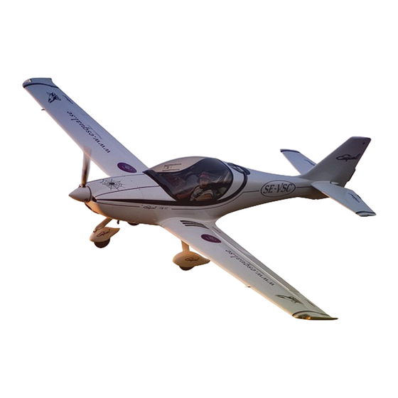
ESQUAL VM-1C
NOTICE
The information contained in this manual is to be used as guideline for the owner - pilot.
(Kit built aircraft may vary substantially, therefore good judgment and discretion must be used.)
(Edition 2018-1)
FLIGHT & OPERATION MANUAL ESQUAL VM-1
Page 1 of 54
Advertisement
Table of Contents

Summary of Contents for Esqual VM-1C
- Page 1 The information contained in this manual is to be used as guideline for the owner - pilot. (Kit built aircraft may vary substantially, therefore good judgment and discretion must be used.) (Edition 2018-1) FLIGHT & OPERATION MANUAL ESQUAL VM-1 Page 1 of 54...
- Page 2 The parachute handle safety pin can be removed at the pilots discretion before flight. Failure to do so may result in the pilots' inability to deploy the parachute due to incapacity, adverse G and or aerodynamic forces resulting from mid air collision or loss of control. FLIGHT & OPERATION MANUAL ESQUAL VM-1 Page 2 of 54...
-
Page 3: Amendment Record
Arsi AB – Esqual www.arsi.se AMENDMENT RECORD Issue Details of change Date Auth by Initial issue 2018-10-15 SA / AA FLIGHT & OPERATION MANUAL ESQUAL VM-1 Page 3 of 54... - Page 4 CHAPTER 0 INTRODUCTION CHAPTER 1 GENERAL INFORMATION 1.1 CHARACTERISTICS 1.2 DESCRIPTION 1.3 REFUELING 1.4 HOW TO MOVE THE ESQUAL WHEN STOPPED 1.5 ANCHORING 1.6 BOARDING 1.7 CANOPY CARE 1.8 COMPOSITE & GEL COAT CARE 1.9 SYMBOLS AND ABBREVIATIONS CHAPTER 2...
- Page 5 8.2 REFERENCE DATUM LINE (RDL) AND CENTER OF CRAVITY (C.G.) LIMITS 8.3 CENTER OF GRAVITY CALCULATIONS OF AN EMPTY AIRCRAFT 8.4 HISTORY AND WEIGHTS 8.5 MINIMUM EQUIPMENT LIST 8.6 ADDITIONAL EQUIPMENT LIST FLIGHT & OPERATION MANUAL ESQUAL VM-1 Page 5 of 54...
- Page 6 The pilot in command shall comply with all requirements, procedures and limitations with respect to the operation of the aircraft set out in the Flight & Operation Manual for the Esqual. It is the owner’s responsibility to incorporate in this manual all amendments and to enter the data of incorporation and his signature on the appropriate amendment Record Sheet.
-
Page 7: General Information
CHAPTER 1 GENERAL INFORMATION 1.1 CHARACTERISTICS 1.2 DESCRIPTION 1.3 REFUELING 1.4 HOW TO MOVE THE ESQUAL WHEN STOPPED 1.5 ANCHORING 1.6 BOARDING 1.7 CANOPY CARE 1.8 COMPOSITE & GEL COAT CARE 1.9 SYMBOLS AND ABBREVIATIONS FLIGHT & OPERATION MANUAL ESQUAL VM-1... - Page 8 Arsi AB – Esqual www.arsi.se 1.1 CHARACTERISTICS FLIGHT & OPERATION MANUAL ESQUAL VM-1 Page 8 of 54...
- Page 9 The cockpit seats are side by side. The landing gear of the Esqual has a classic tricycle gear which is made of 7075 T6 aluminum grade. The main gear legs are suspended in the main carry through beam together with the reinforced wing spar zone.
- Page 10 The easiest way to move the Esqual backwards is done according to the picture below. 1.5 ANCHORING PLACES In case you have to park the Esqual on a ramp (outside hangar), we recommend anchoring it to the floor with ropes attached to the external flap hinge and if needed also at the propeller hub.
-
Page 11: Symbols And Abbreviations
(de-lamination) on the pieces subject to higher mechanical efforts (wing main spar). When in doubt ask your authorized dealer before flying again. Protect the Esqual from humidity and extreme temperature changes with covers if it has to be stored outside for a few days. - Page 12 A. Rotax 912 ULS Engine 2.5 OPERATING SPEEDS & LIMITS A. Rotax 912 ULS Engine 2.6 PROPELLER A. Duc swirl inconell 2.7 AIRCRAFT OPERATING LIMITATIONS 2.8 ELECTRICAL SYSTEM 2.8 RESCUE SYSTEM FLIGHT & OPERATION MANUAL ESQUAL VM-1 Page 12 of 54...
-
Page 13: Engine Type
2.3 PERFORMANCE DATA A. Rotax 912 ULS Engine Take-off performance (73.5 kW) at 5.800 rev/min. Maximum continuous performance (69.0 kW) at 5.500 rev/min. Acceleration 5 seconds maximum at –0.5 G FLIGHT & OPERATION MANUAL ESQUAL VM-1 Page 13 of 54... - Page 14 Max. 5 min.: 850°C Max. T/O: 880°C 2.6 PROPELLER C. Duc Swirl inconell The Esqual is equipped with a Duc Swirl inconell, a three blade carbon fiber, ground adjustable propeller. Diameter: 1660mm Pitch: Ground adjustable (25,5 (+ -1) deg, measured 25% in from tip)
-
Page 15: Aircraft Operating Limitations
Rotax 912 S 277 kg 13 kg 472,50 kg Allowed manoeuvres: The Esqual structure does not restrict manoeuvres, but ultra-lights and experimental aircraft are not cleared for aerobatics. Flight load factors: Maximum load: “+4G” & “-2G” Ultimate load: “+6G” & “-3G”... -
Page 16: Electrical System
The high starter motor current is switched by a relay mounted on the firewall. The starter relay is energised when the Master switch is ON and the starter key switch, mounted on the instrument panel, is turned. FLIGHT & OPERATION MANUAL ESQUAL VM-1 Page 16of 54... - Page 17 12 kg of force. The handle is located on the instrument panel. The parachute canopy is filled gradually to decelerate the aircraft and prevent sudden forces which could damage the aircraft. FLIGHT & OPERATION MANUAL ESQUAL VM-1 Page 17of 54...
- Page 18 3.2 Operating limitations markings in the EFIS / Panel 3.3 Passenger warning 3.4 “NO INTENTIONAL SPINS” 3.5 Miscellaneous placards and markings A. Rotax 912 ULS Engine 3.6 Type placard 3.7 Minimum equipment FLIGHT & OPERATION MANUAL ESQUAL VM-1 Page 18of 54...
- Page 19 Instr. panel 3.6 Type placard The stainless steel type placard is placed on the firewall inside the engine compartement. CALL SIGN Type: Esqual VM 1C Arsi AB Man. date: XX_XX_XX S/N: XXX-XXX FLIGHT & OPERATION MANUAL ESQUAL VM-1 Page 19of 54...
- Page 20 Arsi AB – Esqual www.arsi.se 3.7 Minimum equipment: EFIS / Engine Monitoring EFIS / Compass FLIGHT & OPERATION MANUAL ESQUAL VM-1 Page 20of 54...
- Page 21 Arsi AB – Esqual www.arsi.se CHAPTER 4 MAINTENANCE MANUALS 4.1 INTRODUCTION 4.2 AIRFRAME MAINTENACE 4.3 ENGINE MAINTENACE 4.4 PROP MAINTENANCE 4.5 RESCUE SYSTEM MAINTENANCE 4.6 FUEL SYSTEM MAINTENANCE 4.7 ELECTRICAL SYSTEM MAINTENANCE FLIGHT & OPERATION MANUAL ESQUAL VM-1 Page 21of 54...
- Page 22 4.1 INTRODUCTION As with any Precision Machine, your new ESQUAL VM 1C will take good care of you in the air as long as you take good care of it on the ground. One thing you will appreciate is that your Esqual was designed to last a long time.
- Page 23 Arsi AB – Esqual www.arsi.se Pedals / Hydralics system Rudder wire connection FLIGHT & OPERATION MANUAL ESQUAL VM-1 Page 23of 54...
- Page 24 Arsi AB – Esqual www.arsi.se Elevator hinge/supports Push/pull system FLIGHT & OPERATION MANUAL ESQUAL VM-1 Page 24of 54...
- Page 25 Arsi AB – Esqual www.arsi.se Flap chain FLIGHT & OPERATION MANUAL ESQUAL VM-1 Page 25of 54...
-
Page 26: Fuel System Maintenance
Check the fuel hoses and connections to make sure that there is no leaking/wearing. Make sure that there are no signs of agerelated cracks, change if needed. Check that the fuel filters are clean, change if needed. FLIGHT & OPERATION MANUAL ESQUAL VM-1 Page 26of 54... -
Page 27: Electrical System Maintenance
An analogue or electronic voltmeter mounted on the instrument panel monitors the battery voltage. Normal readings lie in the range 12 to 14.4 volts. (This circuit diagram can vary, depending on avionics/equipment) FLIGHT & OPERATION MANUAL ESQUAL VM-1 Page 27of 54... - Page 28 5.7 CHECK BEFORE TAKING OFF 5.8 TAKE OFF 5.9 CLIMB 5.10 CRUISE 5.11 DESCENT 5.12 APPROACH 5.13 DOWNWIND 5.14 BASE LEG 5.15 LANDING 5.16 BALKED LANDING 5.17 AFTER LANDING 5.18 NORMAL OPERATING DATA FLIGHT & OPERATION MANUAL ESQUAL VM-1 Page 28of 54...
- Page 29 Arsi AB – Esqual www.arsi.se FLIGHT & OPERATION MANUAL ESQUAL VM-1 Page 29of 54...
-
Page 30: Cockpit Layout
Effective ground control while taxiing is accomplished through the differential brakes. Left brake pedal to steer left and right brake pedal to steer right. Both to stop the aircraft straight forward. FLIGHT & OPERATION MANUAL ESQUAL VM-1 Page 30of 54... -
Page 31: Throttle Lever
The direction of movement is the same as for the stick. 26 RESCUE SYSTEM PARACHUTE LAUNCH The ballistic parachute lever is located at the front central panel. Please see the 2.9 RESCUE SYSTEM section for info. FLIGHT & OPERATION MANUAL ESQUAL VM-1 Page 31of 54... -
Page 32: Pre-Flight Inspection
Arsi AB – Esqual www.arsi.se 5.2 PRE-FLIGHT INSPECTION FLIGHT & OPERATION MANUAL ESQUAL VM-1 Page 32of 54... - Page 33 Check brake system for leakage and proper functionality Fuselage (8) Surface Look for knocks or damage Static ports Open and free of dirt or ice Parachute trapdoor Not obstructed and clean FLIGHT & OPERATION MANUAL ESQUAL VM-1 Page 33of 54...
- Page 34 Check hinges, ball-socket joint, damage, free movement and dirt Pitot tube Remove cover and check the opening Main wheel (22) Check tires inflation 2.0 BAR and status of wheel assembly. Brake system for leakage and proper functionality FLIGHT & OPERATION MANUAL ESQUAL VM-1 Page 34of 54...
-
Page 35: Before Starting Engine
Turn on the magnets again and now with the throttle at 1/3 open press the start button. Pull the throttle to idle immediately after you have started the engine. FLIGHT & OPERATION MANUAL ESQUAL VM-1 Page 35of 54... - Page 36 Attention: The drop in revolution with only one magnet should not be superior to 300 RPM. The variation between both magnets should be less than 150 RPM at 4,000 (revolutions, turns). FLIGHT & OPERATION MANUAL ESQUAL VM-1 Page 36of 54...
- Page 37 Once desired height is established, accelerate until the required speed and adjust power. 5.11 DESCENT The Esqual is a very clean, low drag, aerodynamic aircraft which accelerates very rapidly to its cruising speed and when the throttle is retarded it looses speed very slowly maintaining a lot of energy.
- Page 38 Retard for speed 110 km/h and start descent Trim Trim for glide path Straight final Speed Trim speed to 110 km/h until reaching threshold (IF using full flaps set the speed at 95km/h) FLIGHT & OPERATION MANUAL ESQUAL VM-1 Page 38of 54...
-
Page 39: Balked Landing
Best angle of climb speed = 140 km/h 0° flaps Glide ratio speed (19:1) = 140 km/h Stall speed at gross weight = 95 km/h Stall speed at gross weight (full Flapps) = 63 km/h FLIGHT & OPERATION MANUAL ESQUAL VM-1 Page 39of 54... -
Page 40: Emergency Procedures
PREVENTION 6.3 AIRSPEED FOR EMERGENCY OPERATION 6.4 ENGINE FAILURES 6.5 FIRES 6.6 DITCHING 6.7 ICING 6.8 STALL WITHOUT ENGINE 6.9 STALL WITH ENGINE 6.10 SPIN 6.11 LANDING WITH FLAT MAIN TIRES FLIGHT & OPERATION MANUAL ESQUAL VM-1 Page 40of 54... -
Page 41: Airspeed For Emergency Operation
Landing without flaps 110 km/h - FINAL 6.4 ENGINE FAILURES 1. Engine failures during take off a) Throttle: Idle b) Brakes: Apply c) Magnets: Off d) Master: e) Remove from runway and inspect FLIGHT & OPERATION MANUAL ESQUAL VM-1 Page 41of 54... - Page 42 Master switch: OFF e) Cabin heat: OFF f) Airspeed: 200 km/h (or faster if necessary) to provide an incombustible mixture g) Forced landing: Execute as described in power off forced landing FLIGHT & OPERATION MANUAL ESQUAL VM-1 Page 42of 54...
- Page 43 Set up descent at best glide speed – 140 km/h flaps up b) Level out just above water – flaps 30° c) Burn off excess speed and land at minimum speed FLIGHT & OPERATION MANUAL ESQUAL VM-1 Page 43of 54...
- Page 44 All the rest of the procedure remains the same as in “stall without engine”. 6.10 SPIN Spin practice is not authorized on ultra lights. The Esqual spins like a normal aircraft and respond immediately to the normal spin recovery procedure.
-
Page 45: Flight Performance
Arsi AB – Esqual www.arsi.se CHAPTER 7 FLIGHT PERFORMANCE 7.1 TAKE OFF DISTANCE 7.2 LANDING DISTANCE 7.3 CLIMB 7.4 CRUISE SPEED 7.5 AIRCRAFT RANGE 7.6 FUEL CONSUMPTION 7.7 MAXIMUM ALTITUDE FLIGHT & OPERATION MANUAL ESQUAL VM-1 Page 45of 54... -
Page 46: Take Off Distance
At an economic cruise speed of 200 km at 4500 RPM (<65%) and at an altitude of 1500 meters the range is approx. of 1400 km. The wind factor is not considered. FLIGHT & OPERATION MANUAL ESQUAL VM-1C Page 46of... -
Page 47: Maximum Altitude
A take off with less than 10 l of fuel in the tanks is FORBIDDEN. 7.7 MAXIMUM ALTITUDE With a weight of 472,5kg. Standard atmosphere ICAO, the Esqual has shown its capacity to climb to 5000 m (15250 ft) equipped with the Rotax 912 ULS engine. -
Page 48: Weight And Balance
8.2 REFERENCE DATUM LINE (RDL) AND CENTER OF CRAVITY (C.G.) LIMITS 8.3 CENTER OF GRAVITY CALCULATIONS OF AN EMPTY AIRCRAFT 8.4 HISTORY AND WEIGHTS 8.5 MINIMUM EQUIPMENT LIST 8.6 ADDITIONAL EQUIPMENT LIST FLIGHT & OPERATION MANUAL ESQUAL VM-1C Page 48of... -
Page 49: Empty Weight
The horizontal reference line is in the center of the cockpit frame. Esqual VM 1C - ROTAX 912ULS Most FWD limit mm AFT of RDL Most AFT limit mm AFT of RDL FLIGHT & OPERATION MANUAL ESQUAL VM-1C Page 49of... - Page 50 4. Place the total value of weight and torque on row 11 5. Divide "Totalt torque" with "Total weight" on row 11 6. The result on row 11 is your actual CG in mm 7. Allowed CG (in flight) 794-937 mm FLIGHT & OPERATION MANUAL ESQUAL VM-1C Page 50of...
- Page 51 Arsi AB – Esqual www.arsi.se B. Esqual VM 1C – ROTAX 912 ULS Arm (mm) Weight (kg) Moment kg/mm Front wheel -258 Left wheel 1015 Right Wheel 1015 1° Pilot 1157 2° Pilot 1157 Luggage (max 18 kg) 1900 Fuel...
-
Page 52: Minimum Equipment List
Flight manual EFIS / Eng mon instr Fuel pump 8.6 ADDITIONAL EQUIPMENT LIST Ballistic Parachute Radio Transponder Dual brakes Accessory Arm (mm) Weight (kg) Moment( kg/mm) FLIGHT & OPERATION MANUAL ESQUAL VM-1C Page 52of...
Need help?
Do you have a question about the VM-1C and is the answer not in the manual?
Questions and answers