Advertisement
Quick Links
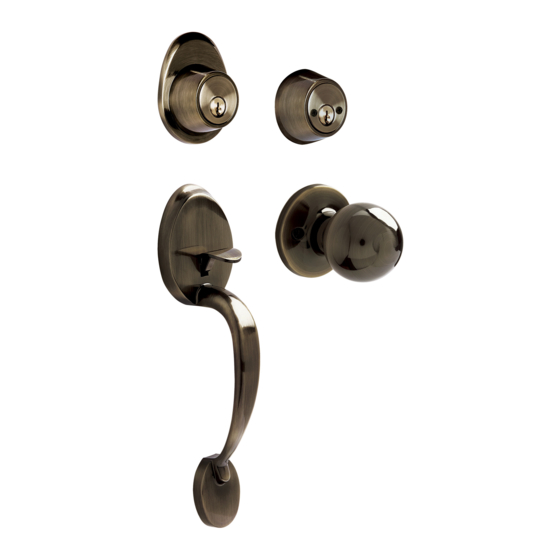
DETAILED SCHEME PARTS
DIBUJO DETALLADO DE PARTES
Five pin tumbler cylinder
Exterior rose
Cilindro de cinco pernos
Escudo exterior
Tail piece
Regleta
Screws
Tornillos
Spindle
Leva
Latch
Handleset exterior
Pestillo
operation
Exterior operado por
gatillo
Tail piece
Regleta
Spindle
Leva
Latch
Pestillo
Screws
Tornillos
Door front
Frente de la puerta
1
Canto de la puerta
2
Mark the center of the hole where the deadbolt will be mounted. (The distance to the rim of the door must be select between two possible sizes, 60 or 70 mm)
Draw the circle of the drill where the deadbolt will be set up with an outer diameter of 54 mm (2-1/8")
Marcar el centro del agujero donde se montará el cerrojo (se debe seleccionar la distancia al canto de la puerta entre las dos medidas fijas posibles, 60 ó 70 mm)
Dibujar el círculo para la perforación donde se instalará el cerrojo con un diámetro exterior de 54 mm. (2 1/8")
3
Drill carefully according to the previously mentioned sizes, making first the bigger hole and then the rim of the door.
With a wood chisel, groove 3 mm depth where the strike of the deadbolt and handleset will fall.
Perfore cuidadosamente la puerta utilizando un taladro con sierra rotativa según las medidas anterioremente citádas y
haciendo primero el agujero mayor y luego el del canto de la puerta.
Ranurar a 3 mm de profundidad con un formón la caja donde va la placa del cerrojo y de la cerradura de gatillo.
4
This latch is adjustable. To adjust to position 2 3/4" (70 mm),
pull the square spindle until it reaches 2 3/4" (70 mm)
position.
Este picaporte es ajustable. Para ajustarlo a la posición de 2
3/4" (70 mm), jale la leva cuadrada hasta que llegue a la
posición
2 3/4" (70 mm).
6
Outside
Exterior
Inside
Interior
NOTES TO CONSIDER:
Original parts included on the box should be used to get
proper set up of the lock.
By replacing parts in the lock the warranty will be void.
Read carefully the installation instructions and when in doubt
seek help from authorized dealer or in the store you bought
this product.
Remember that this lock will fit any door up to 1 3/4" (45 mm)
of thickness.
HANDLESET INSTALLATION INSTRUCTIONS AND TEMPLETE
INSTRUCTIVO, INSTALACION Y PLANTILLA PARA CERRADURA DE GATILLO
Interior thumbturn rose
Escudo mariposa interior
Interior rose
Escudo interior
Tail piece
Regleta
Prepared door
Five pin tumbler cylinder
Puerta preparada
Cilindro de cinco pernos
Interior free-acting Knob/Lever
Perilla/Manija siempre libre
Assemble screws
Tornillos de montaje
Interior fixing miniplate
Mini placa sujetadora interior
Assemble screw
Tornillo de montaje
Use the template, in which the holes are drawn, to mark distances and centers to drill.
Mark the rim center of the door and decide the distance to the main lock. It's recommended 140 mm between both locks.
Draw the circle for the drill of the deadbolt in the rim of the door, it's recommended 24 mm (15/16") of diameter.
In the rim of the door, draw the area in which the plate of the deadbolt will go.
Draw the circle for the interior fixing miniplate 8.5 mm (11/32") hole.
Usar la plantilla donde estan dibujados los agujeros para marcar las distancias y centros a perforar.
Marcar el centro del canto de la puerta y decidir la distancia a la cerradura princial (se recomienda 140 mm entre las dos cerraduras.
Dibujar el círculo para la perforacíon del cerrojo en el canto de la puerta 24 mm (15/16") de diámetro.
Door rim
Dibujar en el canto de la puerta el área donde irá la placa del cerrojo.
Dibujar el círculo para la perforación de 8.5 mm (11/32") donde va la miniplaca sujetadora interior.
DEADBOLT/LATCH SET
AJUSTE CERROJO/PICAPORTE
Turn the spindle the way is shown in the figure.
Adjust the backset to 60 mm or 70 mm.
Turn the spindle counter clockwise. (Use No. 1 as reference)
Gire el cilindro como se muestra en la figura
Ajuste la distancia del centro a 60 mm ó 70 mm
Gire el cilindro en sentido contrario a 1
The deadbolt must be installed with the arrow
upward.
El cerrojo deberá instalarse con la flecha
hacia arriba.
SECURING THE LOCK
FIJACION DE LA CERRADURA
With the deadbolt bar
pushed outside, place
the exterior inserting
the tail piece in the
spindle in vertical
position.
With the key, pull the
deadbolt bar.
Estando la barra del
cerrojo hacia afuera,
colocar el escudo
exterior insertando la
a en la leva en
posición vertical.
Retraer la barra del
cerrojo con la llave.
Insert the handleset
exterior operation
through the latch
holes as it is shown.
Inserte el exterior
Outside
operador por gatillo
Exterior
introduciendo los
postes de ésta unidad
por las ranuras del
picaporte como se
muestra en la imagen.
NOTAS IMPORTANTES:
Deberán de usarse las partes originales contenidas en esta
caja para el correcto armado e instalación de la cerradura.
Al sustituir partes se pierde la Garantía.
Lea completamente las instrucciones de instalación y si tiene
alguna duda consulte al distribuidor que le vendió el
producto.
Recuerde que esta cerradura puede instalarse en puertas de
hasta 45mm (1 3/4") de espesor.
Power drill
Hole saw
Taladro
Cortacírculos
1 1/4"
right door
puerta
derecha
Door handling is determined by standing outside the place/room and
looking where the hinges are placed. If they are placed on the right side the
door is right and left if the hinges are placed on the left side.
El sentido de apertura de las puertas se determina situándose en la parte
exterior de la habitación de frente a la puerta y observando la posición de
las bisagras, si las bisagras estan colocadas en el lado derecho la puerta es
derecha mientras que si estan colocadas en el lado izquierdo, será puerta
izquierda.
DOOR PREPARATIONS
PREPARACION DE LA PUERTA
5
Squared spindle
Leva cuadrada
2
3/8"
2
3/4"
With the deadbolt
reserved, place the interior
with cylinder or thumbturn.
For the cylinder function,
the tail piece must be
introduced in the spindle
in vertical position.
For the thumbturn
function, the spindle must
be introduced in the
thumbturn groove.
Con el cerrojo retraido
colocar el escudo interior
con cilindro ó mariposa.
Para la función de
cilindro, la regleta se
introduce en la leva en
posición vertical. Para la
función mariposa, la
regleta exterior se
introduce en la ranura de
la mariposa.
Use both assembly
screws to fix the
free-acting knob
fastening by hand firstly
then use the screwdriver.
Fix the inside fixing
miniplate with its
assembly screw.
The lock is installed.
Coloque ambos tornillos
de montaje enla perilla
siempre libre. Comienze a
atornillar con la mano.
Termine de fijar con
desarmador de cruz.
Coloque el tornillo de
montaje en la miniplaca
Inside
sujetadora interior.
Interior
Su cerradura está
instalada.
TOOLS NEEDED
HERRAMIENTAS REQUERIDAS
Drill bit
Screwdriver
Broca
Desarmador
3/32"
#1
1/4"
#2
15/16"
DETERMINING DOOR HANDLING
DETERMINAR EL SENTIDO DE LA PUERTA
interior
exterior
Drill 2-1/8"
(54 mm) hole
Agujero pasado
2-1/8" (54 mm)
de diámetro
Drill 11/32"
(8.5 mm) hole
Agujero pasado
11/32" (8.5 mm)
de diámetro
DEADBOLT/LATCH INSTALLATION
INSTALACION DEL PICAPORTE/CERROJO
Insert the deadbolt in the hole rim of
the door, keeping the bar outside.
Fasten the mechanism to the rim of
the door edged equal the strike to
the rim surface.
Inserte el cerrojo en el agujero del
canto de la puerta manteniendo
hacia afuera la barra.
Atornille el mecanismo al canto de la
puerta hasta que quede la placa a
"paño" con la superficie.
Slide the latch through 15/16"door
hole as it is shown. Use the two
screws supplied and fasten.
Deslice el picaporte a la puerta como
se muestra en la imagen y atornille.
STRIKE INSTALLATION
INSTALACION DE LA CONTRA
7
Wood Chisel
Pencil
Formón
Lápiz
left door
puerta
izquierda
Drill 15/16"
(24 mm) hole
Agujero 15/16"
(24 mm)
de diámetro
Install the strike in the
door frame using the
deadbolt and lockset
height to make the
necessary drills.
Instalar la contra en el
marco de la puerta
utilizando la altura del
cerrojo y la cerradura
para hacer las
perforaciones
necesarias.
Advertisement

Related Manuals for Lock LGAL10LA


Summary of Contents for Lock LGAL10LA
- Page 1 Use the template, in which the holes are drawn, to mark distances and centers to drill. Mark the rim center of the door and decide the distance to the main lock. It’s recommended 140 mm between both locks. Draw the circle for the drill of the deadbolt in the rim of the door, it’s recommended 24 mm (15/16") of diameter.
- Page 2 The warranty is not applicable if the product does not show the LOCK brand, if the product is worn out by its daily use, shows signs of abuse, damage, its original composition has been altered, or specifies a different warranty.