Table of Contents
Advertisement
Quick Links
USER MANUAL
MachineMotion Controller Safety Guide (V1E0+)
MachineMotion Safety
v1.0
Contents
Overview
MachineMotion Safety IO
MachineMotion Behavior in
Child Safety Configuration
Overview
This guide describes the safety configurations of MachineMotion V1E0 and later V1 versions. It also shows how to connect MachineMotion to Vention safety
peripherals and have a functional safety configuration.
The goal of the safety system is to power off all actuators connected to the MachineMotion controller immediately upon an E-stop event.
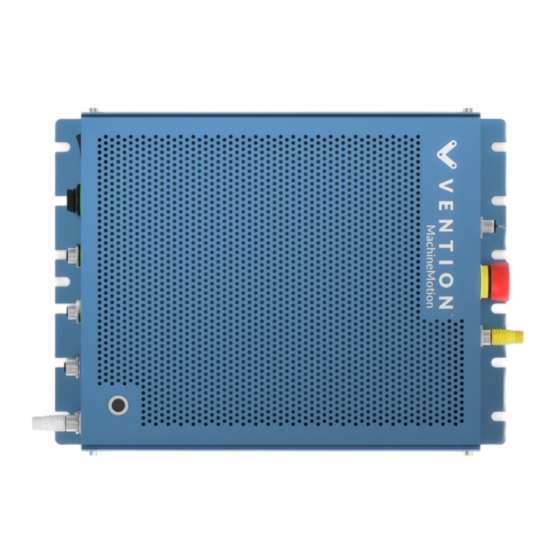
MachineMotion Safety IO
Three main components dictate the safety configuration of the MachineMotion: The E-stop button, the SAFETY IN and the SAFETY OUT plugs. These
components are illustrated in the figure below.
Updated: Friday, July 16th 2021
Advertisement
Table of Contents

Related Manuals for Vention MachineMotion V1E0

Summary of Contents for Vention MachineMotion V1E0
-
Page 1: Table Of Contents
Child Safety Configuration Overview This guide describes the safety configurations of MachineMotion V1E0 and later V1 versions. It also shows how to connect MachineMotion to Vention safety peripherals and have a functional safety configuration. The goal of the safety system is to power off all actuators connected to the MachineMotion controller immediately upon an E-stop event. -
Page 2: Status Led Indications
MachineMotion controller back panel The following table describes the functionality of each component MachineMotion Description connector Used to connect other safety devices that can place MachineMotion in an emergency stop mode (This input should be fed SAFETY IN by a redundant dry contacts) SAFETY OUT Used to trigger and place other devices in an emergency stop mode (redundant dry contacts, normally closed) When pressed, the E-stop button places the system in emergency stop mode. -
Page 3: Machinelogic Software Termination And Io Sate
If you are not using a pendant, insert the white jumper in the pendant plug on the front panel of the MachineMotion MachineMotion with safety jumpers MachineMotion Behavior in Emergency Stop Mode The emergency stop mode is engaged either by an E-stop button (located on the MachineMotion controller or on the pendant), the SAFETY IN port or a software E-Stop. - Page 4 MachineLogic program The next step would be to add the child sequence to the main sequence. This will ensure that it is running in the background and that it will be executed once an emergency stop occurs: 1. Go to the Main Sequence 2.
-
Page 5: Wiring Vention Safety Peripherals
When disengaging the emergency state, the IO remains at the desired state because this was the last state before the termination of the MachineLogic code. Wiring Vention Safety Peripherals Emergency Stop Switch The goal of the emergency stop switch CE-SA-003-0000 is to power off all actuators connected to the MachineMotion controller immediately. -
Page 6: Safety Interlock Switch
Emergency Stop Switch The SAFETY OUT of the emergency stop switch needs to be connected to the MachineMotion SAFETY IN, as seen in the figure below. Please note, if you want to use multiple emergency stop switches, you have to connect them in series. Beware of connecting the SAFETY IN of the first switch to the SAFETY OUT of the second. -
Page 7: Wiring Multiple Machinemotion
Safety Divider Ports Description (4-pin M12) Port 1 Connect this port to the SAFETY IN of the MachineMotion Port 2 Connect the interlock cable to this port If you only have 1 interlock connector: Connect the appropriate jumper to this port If you have 2 safety interlocks: Connect the cable of the second safety interlock to this port Port 3 If you have more than 2 safety interlocks: Connect this port to a port of a second safety divider and connect the other... -
Page 8: Behavior Of The Parent And
Refer to the second image below. Note, the SAFETY OUT port can be left unconneted, as it is an output and will not trigger an emergency stop. Parent and Child MachineMotion controllers’ safety configuration without safety peripherals Parent and Child MachineMotion controllers’ safety configuration with safety peripherals In addition, if you have more than two MachineMotion, you need to connect the SAFETY OUT of the second MachineMotion to the SAFETY IN of the third MachineMotion. - Page 9 Note, it is recommended to remove the E-stop button on the Child controller. This will allow the Parent controller E-stop to be the only visible and attainable E-stop in the system. Please contact Vention Customer Success team for more support on this procedure.
Need help?
Do you have a question about the MachineMotion V1E0 and is the answer not in the manual?
Questions and answers