
Summary of Contents for frio S1
- Page 1 S1 IoT Heat Trace Controller Operating Manual © Frio 2021 - Rev. 0.3 - Updated 3/2/2021...
-
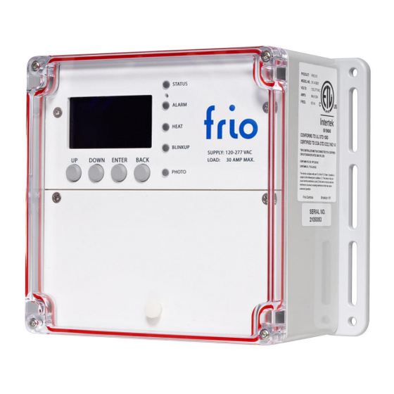
Page 2: Device Diagram
→ → HMI (Human Machine Interface) Wiring Area A. Screen E. High Voltage Connections B. Buttons F. Low Voltage Connections C. LEDs G. Ethernet Connection D. Device Reset 2 | © Frio 2021 - Rev. 0.3 - Updated 3/2/2021... -
Page 3: Table Of Contents
Sensor Failure ..............................13 3.5.3 GFEP Alarms ..............................13 3.5.4 Active Alarms ..............................13 Sensors .................................. 13 3.6.1 RTD ................................13 3.6.2 Thermistor ..............................13 Device Info ................................14 3 | © Frio 2021 - Rev. 0.3 - Updated 3/2/2021... - Page 4 Rebooting the Device ............................23 Clearing Device Settings ............................23 5.8.1 Restore Factory Default Settings ........................23 5.8.2 Clear Network Credentials ..........................23 Offline Devices ..............................23 Firmware Upgrades ............................... 24 4 | © Frio 2021 - Rev. 0.3 - Updated 3/2/2021...
-
Page 5: Introduction
Frio does not warrant the products described herein will meet the user’s requirements nor does it give any warranty about the results that may be obtained by using the products. Frio reserves the right to make changes or improvements to the products described in this manual and to revise this publication at any time. -
Page 6: S1 System Overview
Frio S1-A: Wi-Fi and Ethernet The Frio S1-A can connect to the Frio cloud platform via Wi-Fi 802.11 Dual Band 2.4GHz & 5GHz or wired ethernet connection using a Cat 5 or Cat 6 cable. The device uses an FCC certified Wi-Fi Module and has been tested to the requirements laid out in FCC Part 15 Subpart B. -
Page 7: Manual Control
Force On command, select Cancel Force On from the Main Menu. The Force On feature may also be used with any of the other control modes selected. Users may also force the device on or off via the Frio Cloud platform as described below. -
Page 8: Adjusting The Gfep Trip Level
Adjusting the GFEP Trip Level The GFEP Trip Level on the Frio S1 controller is adjustable from 30 mA to 300mA. Frio does not recommend setting the GFEP threshold above 30 mA. In limited circumstances and always under the guidance of a licensed electrician, the GFEP threshold may be set to a value above 30 mA. - Page 9 2.4GHz 802.11b, 802.11g, and 802.11a networks. To connect a Frio S1-A device to a Wi-Fi Network use the Frio Mobile App. The mobile app will allow you to configure the device via the BlinkUp process and connect to a Wi-Fi network. To clear the Wi-Fi credentials from the device, select Settings from the Main Menu, then select Advanced Settings from the Settings Menu.
-
Page 10: S1-C Cellular Internet Connection
The S1-A will attempt to connect via TCP port 31314. If this fails, it will attempt to use TCP port 993, which is typically open by default for email traffic. Should both 31314 and 993 be closed, it will try 443. The S1-A does not use UDP. -
Page 11: Bacnet
The following table includes the BACnet Points List that will be available on future firmware versions. The points list is included to aid in the design of systems that will communicate with the Frio S1 via BACnet. For the latest information on BACnet compatibility, please contact Frio at info@frio.co. -
Page 12: Dry Contact
The Frio S1 is equipped with a dry contact to provide users with a low voltage alarm output option. The dry contact is normally closed and opens when the Frio S1 has an alarm signal. The contacts are rated for 2 A maximum at 250 VAC and are compatible with 14-24 AWG wires. -
Page 13: Sensor Failure
Thermistor The Frio S1 should only be used with the Frio thermistor. The Frio thermistor is a 10k NTC thermistor with ± 1% accuracy. The Frio thermistor has an operating range of -40°C to 105°C and an international protection rating of IP68. -
Page 14: Device Info
Dry Contact Alarm: Normally Closed, Open on Alarm (contacts rated for 2 A max at 250 VAC, 14-24 AWG) Connectivity S1-A: WI-FI 802.11 Dual Band 2.4 GHz & 5 GHz and Ethernet (RJ45, Cat 5 or 6) See operating manual for firewall information... -
Page 15: Agency Approvals
No. 14 for Ground-Fault Sensing and Relaying Equipment. Both the S1-A and S1-C devices comply with part 15 of the FCC Rules. Operation is subject to the following two conditions: (1) This device may not cause harmful interference, and (2) this device must accept any interference received, including interference that may cause undesired operation. -
Page 16: Installation Instructions
NSPECTION AND LANNING 1. Inspect the Frio S1 controller for any damage that may have occurred during shipping. 2. Layout and plan the heat tracing system, including all sensors, wiring, conduit, and junction boxes. 3. Determine the controller location. The controller should be mounted on a fixed vertical surface. The controller may be mounted outside but should not be mounted in direct sunlight to reduce the chance of condensation forming in the controller. -
Page 17: Step 3: Low Voltage Connections
3. For more information on sensor compatibility and setup, please consult the owner’s manual. Figure 3: Top view of the Frio S1 controller with the wiring cover removed, showing all possible wiring connections. NOTE: THE SYSTEM SHOULD NEVER BE ENERGIZED WHEN THE WIRING COVER IS NOT IN PLACE. -
Page 18: Step 6: Internet Connection (Blinkup)
2. Complete App Setup and enter all required information. 3. Connect to the S1 Controller via BlinkUp as directed in the Frio App. 4. Follow the in-app instructions to connect the Frio S1 controller to the internet and the Frio Cloud Platform. 4.7 S... -
Page 19: 4.8 Gfep Test Form
TEST PERFORMED BY COMPANY NOTE: THIS TEST FORM MUST BE RETAINED BY THOSE IN CHARGE OF THE BUILDING'S ELECTRICAL INSTALLATION IN ORDER TO BE AVAILABLE TO THE AUTHORITY HAVING JURISDICTION. 19 | © Frio 2021 - Rev. 0.3 - Updated 3/2/2021... -
Page 20: Menus, Navigation And Operation
Sections 5.7, 5.8, and 5.9 cover rebooting the device, clearing device settings and offline devices. 5.1 LEDS There are 5 LED light pipes on the front faceplate of the Frio S1. ▪ Status – LED will be GREEN if the device is operating properly with no alarms. -
Page 21: Settings
NOTE: WHEN USING THE HIGH CURRENT ALARM WITH SELF-REGULATING HEAT TRACE, IT IS HIGHLY RECOMMENDED TO USE A DELAY OF AT LEAST 300 SECONDS TO AVOID ALARMING DUE TO INRUSH CURRENT WHEN THE HEAT TRACE IS ACTIVATED. 21 | © Frio 2021 - Rev. 0.3 - Updated 3/2/2021... -
Page 22: Start Up
3.4.1 and 3.4.2. After the device checks for a connection it will display the Frio logo on the main screen while loading device firmware from memory. Loading the firmware can take several seconds. When the firmware is loaded, the display will show the main screen and the device is ready to use. -
Page 23: Rebooting The Device
Frio recommends disabling networking on offline devices as this will disable the network connection alarm. Offline devices will not have access to the Frio Cloud platform and will not be able to use any cloud features. Offline devices will not have access to any firmware updates. -
Page 24: Firmware Upgrades
When an update occurs, the device will restart, shutting off the heating system if it is on. Once the update is complete, the device will resume normal operation. Updates typically take less than one minute to complete. 24 | © Frio 2021 - Rev. 0.3 - Updated 3/2/2021...
Need help?
Do you have a question about the S1 and is the answer not in the manual?
Questions and answers