Table of Contents
Advertisement
Quick Links
Advertisement
Table of Contents

Summary of Contents for Opsens ProSens
- Page 1 ProSens with PSP, PSM and PSR modules...
- Page 3 ProSens with PSP, PSM and PSR modules Opsens inc 2014 Cyrille-Duquet, Suite 125 Québec, QC G1N 4N6, Canada Tel. : +418-682-9996 Fax: +418-682-9939 info@opsens.com www.opsens.com © Opsens Inc. IMP0041 ProSens with PSP, PSM, PSR modules rev1.1.doc...
- Page 4 © Opsens Inc. IMP0041 ProSens with PSP, PSM, PSR modules rev1.1.doc...
- Page 5 + 418-682-9939 E-MAIL info@opsens.com PACKAGING FOR SHIPMENT If the product must be shipped to a different location or returned to Opsens for any reason through a common carrier it must be properly packaged to minimize risks of damage. SOFTWARE LICENSE AGREEMENT This product contains intellectual property, i.e.
- Page 6 WARNING: VOLTAGE SUPPLY! Use only the wall plug-in power supply delivered with your PicoSens and verifies that the input voltage and frequency are compatible with the power outlet. © Opsens Inc. IMP0041 ProSens with PSP, PSM, PSR modules rev1.1.doc...
-
Page 7: Table Of Contents
Select Folder dialog ............................. 37 6.4.2 File data acquisition ............................. 37 6.4.3 Data acquisition file structure ..........................39 Remote operation and data acquisition ............42 Remote and Local modes ..........................42 © Opsens Inc. IMP0041 ProSens with PSP, PSM, PSR modules rev1.1.doc... - Page 8 © Opsens Inc. IMP0041 ProSens with PSP, PSM, PSR modules rev1.1.doc...
-
Page 9: Instrument Overview
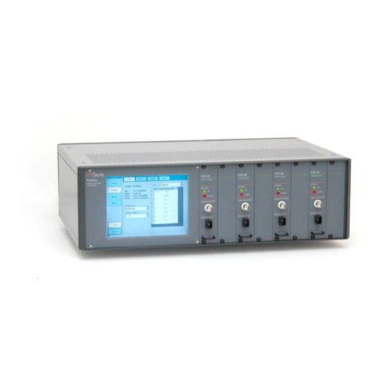
PSM and PSR plug-in measurement modules. Each module has one measuring channel and one analog output. Up to eight modules can be plug into the ProSens chassis. The data output rate of each module is adjustable from 100 to 1000 Hz. Data measurements... -
Page 10: Installation
2. Installation 2.1 Power Connection The ProSens instrument is configured for line voltages of 85 to 265 VAC at line frequency of 47 Hz to 66 Hz. The power rating is 100 W nominal (for eight modules). Verify that the line operating voltage in your area is conforming to the above specifications. -
Page 11: Sensor Connection
3. Sensor connection Opsens fiber-optic sensors or transducers must me mated to the ProSens output connectors (Figures below). The optical connectors provided with the ProSens are usually a square push-pull SC-type mating. Remove the protective cap of the mating, engage the sensor connector with the orientation key properly oriented and push until it clicks into its place. - Page 12 To disconnect, grab the square connector body and just pull Ask for Opsens Fiber-Optic Cleaning Guide for further information on how to clean fiber- optic connectors. As a reminder, Opsens provides you the good practice rules for handling and using fiber optic sensors: Keep the fiber optic connector surface clean –...
-
Page 13: Quick Start Guide
4. Quick Start Guide Step 1: Sensor with Gage Factors must be defined and saved into internal ProSens memory (Sensor submenu (module specific)). Step 2: Module must be associated with one sensor defined into the ProSens (Sensor assignment). Step 3: Sensor must be initialized (select appropriate filtering method and parameters... -
Page 14: Psp, Psr And Psm Modules
5. PSP, PSR and PSM modules The ProSens can be populated with up to 8 modules of either the same type or of different types of modules. Although most functionalities and menus related to each module are similar, there are some differences. Instructions described in section 5 that are module specific are highlighted as follow (module specific). -
Page 15: Instrument Setup
Local Area Network (LAN) - either to Client/server configuration network or to Peer-to- Peer configuration network. 6.1.1 Client/server network You can connect the ProSens instrument to the same network as the computer with a standard LAN cable. The ProSens can be configured either with an automatic IP address obtained through the DHCP server of the network or with a fixed IP address. -
Page 16: Peer-To-Peer Network
Then a dialog will ask you to reboot, press on Yes button to make this new parameters effective. 6.1.2 Peer-to-Peer network In a Peer-to-Peer network configuration, the ProSens Instrument is directly connected to crossover LAN cable a remote computer using a . -
Page 17: Configure Menu: Instrument And Sensor Configuration
Sensor submenu (Figure 6) and thereafter select and assign one of these defined sensors to a particular module (see Channel submenu for sensor selection and assignment). © Opsens Inc. IMP0041 ProSens with PSP, PSM, PSR modules rev1.1.doc... -
Page 18: Psp Module (List Of Sensors Available)
Sensor Type Measurement Computation unit Alternative Unit Temperature °C °F Pressure mmHg Mbar Pressure Pressure P1,P2 Pressure Pressure mbar Torr Strain µe Displacement © Opsens Inc. IMP0041 ProSens with PSP, PSM, PSR modules rev1.1.doc... -
Page 19: Psm Module (List Of Sensors Available)
To copy a sensor, select it from the list and press on the Copy button. The sensor is added to the end of the list (Figure 8) Figure 8 © Opsens Inc. IMP0041 ProSens with PSP, PSM, PSR modules rev1.1.doc... -
Page 20: Channel Submenu
6.2.3.1 Enabling/disabling modules Each module has an ID # which is given by their respective slot position number, from 1 to 8 (1 is the left most slot position) in the ProSens chassis. © Opsens Inc. IMP0041 ProSens with PSP, PSM, PSR modules rev1.1.doc... -
Page 21: Sensor Assignment
Channel menu first select a specific module number (# column). Next select the appropriate sensor definition in the Sensor dropdown sensor list as shown in Figure 13. © Opsens Inc. IMP0041 ProSens with PSP, PSM, PSR modules rev1.1.doc... -
Page 22: Diagnostic (Module Specific)
PSP and PSM Modules Diagnostic Parameter and unit values Description Lamp % Lamp driving level Light Volts Light level Visibility % Visibility level Gain Gain level Vraw V Raw voltage Table 3 © Opsens Inc. IMP0041 ProSens with PSP, PSM, PSR modules rev1.1.doc... - Page 23 If “S. LOST” message appears, turn the instrument OFF and ON again. If the problem still persists, please contact Opsens technical support. During a no signal or slot lost condition, the different outputs of the instrument take the following states or values: ©...
-
Page 24: Psr Module Diagnostic
PSR module. A fault condition results in a “NO SIG” (no signal) or “S. LOST” (slot lost) message being displayed in the Measure-numeric submenu windows (see Figure 23). © Opsens Inc. IMP0041 ProSens with PSP, PSM, PSR modules rev1.1.doc... -
Page 25: Channel Configuration: Digital Noise Reduction Filters
(Not plotted) 6.2.3.4 Channel configuration: digital noise reduction filters The ProSens instrument offers two types of digital noise reduction filters which are the running average filter and the adaptive filter. Press on the Config. Button and select the Filters tab to access to the Filters submenu as shown in Figure 16. Click on the respective radio button to select one of the two filter types and adjust their parameters accordingly as explained next. - Page 26 The Opsens’ adaptive filter can be tough as a discrete first-order low-pass filter with self- adjusting filter time constant. The adjustment range of the filter time constant is bonded between the Tc Low and Tc High parameters (Figure 16).
-
Page 27: Channel Configuration: Zeroing And Offsetting
Zeroing a sensor assigned to a module means to force the data measurements of that selected module to be equal to zero immediately after it is activated and to set the module output in relative temperature measurement. Automatic zeroing is performed by © Opsens Inc. IMP0041 ProSens with PSP, PSM, PSR modules rev1.1.doc... -
Page 28: Channel Configuration: Analog Output Settings
The measurement as a function of the analog output voltage is thus given by: Analog output = [Physical unit] x Scale (Base Unit / Volt) + Offset Base Unit . © Opsens Inc. IMP0041 ProSens with PSP, PSM, PSR modules rev1.1.doc... -
Page 29: Channel Configuration: Config All
Use the Config All - Offsets/Analog Ouput tab submenu to assign the Internal Offset, the Physical Offset, the Analog Scale, or the Analog Offset parameter with the same value for all the modules plugged in the ProSens chassis (See Figure 19). Figure 19 6.2.4 Slot submenu... -
Page 30: I-Source Submenu (Optional)
FRN: Firmware revision number. This number is modified after a firmware upgrade. 6.2.5 I-source submenu (optional) An optional current source can be ordered with the ProSens instrument. This current source is useful for calibrating bridge-wire electro-explosive devices. The I-Source submenu includes basic commands for controlling the current source (Figure 21). -
Page 31: Measure Menu
The Measure menu allows the user to turn ON the data display so the data measurements can be visualized on the color TFT screen of the ProSens instrument. The data measurements can be displayed in three different graphical forms: numeric, line graph and bar graph form. -
Page 32: Line Graph
Opsens technical support S. LOST: Slots Lost. Hardware or software fault prevent the module from sending the data or prevent the ProSens inboard computer to receive the data. Turn OFF and ON the instrument. If the problem persists, contact Opsens technical support. - Page 33 DarkViolet BurlyWood Figure 25 The scaling of the graph is not adjusted automatically. Press on Settings button to adjust the graph scales and to access to other graph options. © Opsens Inc. IMP0041 ProSens with PSP, PSM, PSR modules rev1.1.doc...
- Page 34 These are the minimum and maximum values, the average value and the standard deviation of the signal as well as a NO SIGNAL condition, if any detected. Figure 27 © Opsens Inc. IMP0041 ProSens with PSP, PSM, PSR modules rev1.1.doc...
-
Page 35: Bar Graph
The scaling of the bar graph is not adjusted automatically. Press on Settings button to adjust the graph scales and to access to other graph options such as peak level and alarm indicator (Figure 30). © Opsens Inc. IMP0041 ProSens with PSP, PSM, PSR modules rev1.1.doc... - Page 36 ON, the measurement data are outputted to the Ethernet port as well. Turning OFF the bar graph display or going out of the Measure window immediately stop the data measurement output at the Ethernet port. © Opsens Inc. IMP0041 ProSens with PSP, PSM, PSR modules rev1.1.doc...
-
Page 37: Memory Menu
Figure 30 6.4 Memory menu The ProSens has an internal hard disk option. When enabled, the user can make stand alone real time recording of Gbytes of measurement data. Recorded data is easily transferred on remote computer through the Ethernet interface via a FTP server. At boot up time, the ProSens detects the availability of the hard disk option. - Page 38 Delete all: This button deletes all the files in the current directory. A dialog box prompts the user to confirm the action. © Opsens Inc. IMP0041 ProSens with PSP, PSM, PSR modules rev1.1.doc...
-
Page 39: Select Folder Dialog
The Directory text box indicates in which directory the data file will be saved. To change the current directory, press on the Current directory (…) button next to this box. Figure 33 © Opsens Inc. IMP0041 ProSens with PSP, PSM, PSR modules rev1.1.doc... - Page 40 The acquisition process can be terminated at any time by pressing the Stop button in the Measure \ Numeric submenu window. © Opsens Inc. IMP0041 ProSens with PSP, PSM, PSR modules rev1.1.doc...
-
Page 41: Data Acquisition File Structure
(\t) and each line ends with a Windows™ end of line two characters (\r\n). Each data has a fixed field width of ten characters. © Opsens Inc. IMP0041 ProSens with PSP, PSM, PSR modules rev1.1.doc... - Page 42 <\t> <data channel N> <\r\n> {Data} <data channel 1> <\t> <data channel 2> <\t> ..<data channel N> <\r\n> See also the data acquisition file example on next page © Opsens Inc. IMP0041 ProSens with PSP, PSM, PSR modules rev1.1.doc...
- Page 43 Data acquisition file example (text format): Created: Friday, September 21, 2007 16:12:24 Description: Test 56 – Aircraft XYZ. IDN: Opsens inc., ProSens, SN:15-000007, HRN:5.00.10, FRN:1.18a 07Sep21, LRN:1.06 07Sep17 Sampling rate (Hz): 500 Measure period (s): 0.002 Channel number: 2 Description: Right wing...
-
Page 44: Remote Operation And Data Acquisition
The interface uses the TCP/IP protocol for communication with the instrument. Remote control and data acquisition over the Ethernet interface is done on a ASCII-syntax message level basis using the SCPI command set of the ProSens instrument (SCPI: Standard Commands for Programmable Instrumentation). Therefore the user can create its own remote control software using the various SCPI commands available for the ProSens.
Need help?
Do you have a question about the ProSens and is the answer not in the manual?
Questions and answers