Advertisement
Quick Links
Advertisement

Related Manuals for Laine's Planes Cuda

Summary of Contents for Laine's Planes Cuda
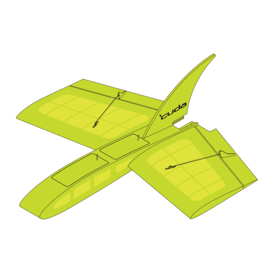
- Page 1 26” & 35” Wingspan Revised: May 30, 2015...
- Page 2 Time spent waiting for glue to dry can be minimized by creating sub-assemblies. Below is a suggested list of suggested sub-assemblies in a suggested build order: Page 3: Fuselage Sides - Parts F1, F8 & F0 Page 3: Motor Mount - Parts M1 (inrunner) or M2, M3 & M4 (outrunner) Page 4: Parts F7 &...
-
Page 3: Fuselage Assembly
Fuselage Assembly Assemble Left & Right Fuselage Sides Out-Runner Mount In-Runner Mount Page 3... - Page 4 Selected Motor Mount 6mm x 3mm Magnets Glue magnets in both parts “F7” 8mm OD x 7.1mm ID x 75mm brass tubing wing sockets Page 4...
- Page 5 Sand front of fuselage flat before attaching parts “N1” & “N2” Sand nose to shape Page 5...
-
Page 6: Hatch Assembly
Hatch Assembly 1/4” x 1/8” Magnet When gluing magnets into parts “H1” & “H5”, make sure the magnets are oriented properly 1/4” x 1/8” Magnet so that they will hold the hatches closed 1/16” x 1” Carbon rod (Hatch Handles) Tip: Covering the hatches will be easier if you wait to install the carbon rod hatch handles after covering. -
Page 7: Vertical Fin Assembly
Vertical Fin Assembly Page 7... -
Page 8: Wing Assembly
Wing Assembly 8-32 Blind Nut 26” & 35” Wing Left wing shown. Remember to build a Left and a Right wing 7mm Od x 5mm Id 12 5/8” long carbon tube spars 35” Wing 26” Wing Page 8... - Page 9 35” Wing 26” Wing 26” Wing 35” Wing Page 9...
- Page 10 Parts W7 are intended to reinforce the hinge mounting locations. 35” Wing 26” Wing 26” Wing Upper Skin Lower Skin 35” Wing 26” Wing 35” Wing Page 10...
- Page 11 Sand Wing leading and trailing edges flat before attaching parts “W5” & “W6” Page 11...
- Page 12 Glue wing tip cap rib on after sanding wing tip flat. 26” Wing Sand leading edge, 35” Wing trailing edge & tip to shape Aileron ribs (Parts “A2”) should be beveled slightly at the thick end prior to assembly to allow sufficient space to attach part “A4”. Use etched lines on part “A1”...
- Page 13 Sand Aileron Sand Aileron leading edge flat leading edge before attaching to shape part “A5”. Hinge Ailerons to trailing edges of wings Page 13...
- Page 14 Use etch marks for proper orientation when attaching servos to part “S1” Page 14...
- Page 15 Final Assembly Wing spars slide into brass tubes. Page 15...
- Page 16 Attach wings using 8-32 x 7/8” long Socket Head screws threaded into the Blind Nuts previously installed in the wings The Center Of Gravity should fall approximately where leading edge of the wing meets the side of the fuselage. Page 16...
Need help?
Do you have a question about the Cuda and is the answer not in the manual?
Questions and answers