
Summary of Contents for Atonometrics Mars
- Page 1 Document Number 880060 Rev. C, November 2020 www.atonometrics.com Copyright © 2020 Atonometrics, Inc. All rights reserved.
-
Page 2: Table Of Contents
Configuration Steps ....................8 Checking Communication ..................10 Wiring ........................... 11 Power ........................11 Cable Options ......................11 Atonometrics-Supplied Cables ................12 User Assembly of Power & RS-485 Cable .............. 13 Protecting Unused Wires ..................14 Mounting ..........................15 Mounting Requirements ..................15 Dimensions ...................... -
Page 3: Product Overview
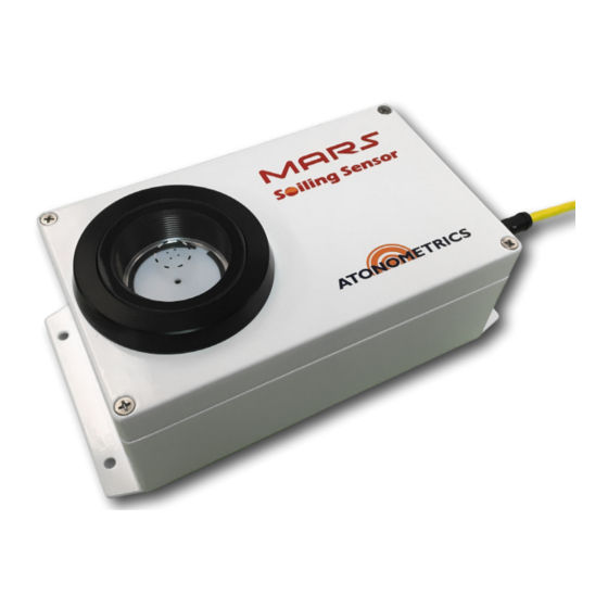
The Mars™ unit requires no water, has no moving parts, is compact and easy to install, and does not require site-specific dust calibration or technician service visits. It is specifically designed to be suitable for a wide range of PV installation types, including small commercial and industrial projects. -
Page 4: Configuration
Ethernet-to-USB adapter, an Ethernet cable, an RS-485 to USB adapter, and a cable for connecting power and RS-485 to your Mars™ unit. (An M12 to RJ45 Ethernet cable is also included with each Mars™ unit for connection to the M12 Ethernet port on SN15000 and higher.) - Page 5 Ethernet Adapter PN 830261-002 To Mars™ M12 Ethernet To PC USB Port Connector Ethernet Cable RS485 Adapter White Purple PN 830256-004 To PC USB Port To Mars™ Orange M12 Power/RS485 Connector DC Power Adapter Black Pink 15 VDC To AC Power...
-
Page 6: Accessing The Web Interface
Accessing the Web Interface After power up, the Mars unit’s soil collection window will light up for a short time and then will go dark. Wait 2-5 minutes for initialization to complete. Configuration is performed by accessing the unit’s internal web interface from your PC using a web browser, such as Chrome, Firefox, or Internet Explorer. - Page 7 Figure 2-2: Web interface 880060_C Page 7 of 25...
-
Page 8: Configuration Steps
10 kilometers. 2.4.3 Checking the Clock The unit’s internal clock must be set to UTC time and is set by Atonometrics prior to shipment. To confirm the clock time, use the web interface (Figure 2-2) to check the clock against another UTC time source, such as a UTC time website. - Page 9 Your Mars™ unit’s default IP address upon shipment from Atonometrics is 10.244.69.66. To change your Mars™ unit’s IP address, enter the new address, as well as any desired subnet mask and gateway, using the web interface (Figure 2-2), then press “Update”.
-
Page 10: Checking Communication
Checking Communication For an example and guidance on checking Modbus communication using third-party software in your data logger or SCADA system, see the Atonometrics application note document 880084 “Testing Modbus Communication on the Mars™ Soiling Sensor”, available via the Atonometrics website in the downloads area for the Mars™... -
Page 11: Wiring
3 Wiring Power The Mars™ unit requires 10-30 VDC and typically draws < 3 W of power in operation. However, use at least a 6 W power supply to provide for inrush and transient currents. Cable Options Each Mars™ unit is supplied with the following: An M12 connector (160375-02) for user assembly of the power/RS-485 cable using user- •... -
Page 12: Atonometrics-Supplied Cables
Atonometrics-supplied 830261 Ethernet cables will have one sealed M12 connector for connection to the Mars™ unit. The other end of the cable will include a non-sealed RJ45 for cable testing purposes. Remove this and use a user-supplied cable gland or sealed connector for installation to your outdoor equipment cabinet. -
Page 13: User Assembly Of Power & Rs-485 Cable
User Assembly of Power & RS-485 Cable In place of purchasing a complete power & RS485 cable from Atonometrics, you may optionally assemble this cable using user-provided wiring materials as listed in Table 3-2 and Figure 3-2. Note that each Mars unit is shipped with a 160377 connector for user wiring. -
Page 14: Protecting Unused Wires
Protecting Unused Wires Protect any unused wires from accidental contact by cutting to unequal lengths, folding back, and insulating, as shown in Figure 3-3. Insulate Figure 3-3: Protecting unused wires from accidental contact 880060_C Page 14 of 25... -
Page 15: Mounting
Figure 4-1 Figure 4-1: Mounting requirements and view of sky To mount the Mars™ unit, use the four mounting holes on the flange of the unit shown in Figure 4-2. To minimize the potential for water entry to the sealed housings, always mount the Mars™ unit with the cables facing down or to the side, as shown in Figure 4-3, and never with the cables facing up. - Page 16 Mounting holes (x4) Figure 4-2: Mounting holes Figure 4-3: Mount with cables down or to the side 880060_C Page 16 of 25...
-
Page 17: Dimensions
Dimensions Figure 4-4: Mars™ dimensions 880060_C Page 17 of 25... -
Page 18: Mounting Accessories
Mounting Accessories Optional flat plate, right-angle, and pole-mountable adjustable-angle mounting accessories are shown in Figure 4-5, Figure 4-6, and Figure 4-7. Figure 4-5: Optional flat mounting plate 610449 (sold separately) 880060_C Page 18 of 25... - Page 19 Figure 4-6: Optional right-angle mounting bracket 610451 (sold separately) Figure 4-7: Optional adjustable bracket kit 810241 for pole mounting (sold separately) 880060_C Page 19 of 25...
-
Page 20: Network Setup
5 Network Setup To configure your Mars™ unit for use on an Ethernet network, set IP addresses and related communication parameters as directed in section 2.4.5. In addition, you may need to open ports in your network firewall, or set port forwarding on your cellular modem. -
Page 21: Modbus
6 Modbus Table 6-1 lists the registers available for your client software to read data from the Mars™ unit. Each numbered register in the table is a 16-bit (2-byte) register. Parameters requiring more than two bytes must be read from sequential registers as indicated by the Register Start and Register End columns. -
Page 22: Troubleshooting
Confirm Mars™ unit’s clock shows accurate UTC time (p. 8) • • Allow Mars™ unit to operate through at least one sunset and night and check the readings the next day (Chapter 9) If needed, visually inspect unit for damage or fouling •... -
Page 23: Maintenance
8 Maintenance Check your Mars™ unit’s clock once per year (see p. 8) and update if needed. 880060_C Page 23 of 25... -
Page 24: Theory Of Operation
An example image is shown on the right in Figure 9-1. A processor inside the Mars™ unit analyzes the image to determine the transmission loss (i.e. the soiling loss) due to the soiling particles. A series of self- calibration marks inside the window provides reference features in the image which aid analysis. -
Page 25: Specifications
10 Specifications Table 10-1: Specifications General Model name Mars Soiling Sensor™ Ambient working temperature -20 to +60 °C Input power 10 to 30 VDC Power consumption <3 W typ. (use 6 W supply for inrush & startup) Transmission loss accuracy ±...
Need help?
Do you have a question about the Mars and is the answer not in the manual?
Questions and answers