
Summary of Contents for FilterSense DynaCHARGE PM 1 Series
- Page 1 Particulate Monitor Model DynaCHARGE™ PM 1 INSTALLATION & OPERATING MANUAL T: (978) 927-4304 | 800 Cummings Center, 355W Beverly, MA 01915 USA | www.fi ltersense.com...
-
Page 3: Table Of Contents
System-Zero Check .................................. 32 Response Testing ..................................33 Factory Testing ..................................33 Troubleshooting ......................... 34 10 Maintenance ..........................35 11 Spare Parts ..........................36 11.1 Electronics Module Replacement ............................36 PM 1 Installation and Operating Manual v1.2 FilterSense © 2016... -
Page 4: Notifications
To assure the best and most efficient technical support, please be prepared with the following information prior to contacting FilterSense. If it is determined that the component must be returned for evaluation/repair, a Return Material Authorization (RMA) number will be issued. You must include the RMA number on the packing slip and mark the outside of the shipping container. -
Page 5: Disclaimer
This document contains important information necessary for proper operation of the product. It is strongly urged that all users of the product read this manual in its entirety. All instructions should be followed properly and any questions that arise should be discussed with FilterSense (A Division of Impolit Environmental Control Corp.). -
Page 6: Safety
Service of individual electronics is limited to replacement of the electronics module. Do not attempt to disassemble electronics. Any components that are not operating properly should be returned to FilterSense for service. PM 1 Installation and Operating Manual v1.2 FilterSense © 2016... -
Page 7: Associated Documentation
Associated Documentation This manual is to be referenced in conjunction with the following FilterSense documentation: Product Information Publication Number Title 228-1077 FilterSense Particulate Monitoring Application and Alarm Guide EXXXX Project Specific Drawings if Applicable PM 1 Installation and Operating Manual v1.2... -
Page 8: Introduction
Monitor with Alarm Relay Outputs and Analog Output Integral or Remote Electronics Graphical Display/Keypad PM 1 PRO-T Advanced, High-Performance Parti- culate 4-20mA Transmitter Integral or Remote Electronics Graphical Display/Keypad PM 1 Installation and Operating Manual v1.2 FilterSense © 2016... -
Page 9: Components
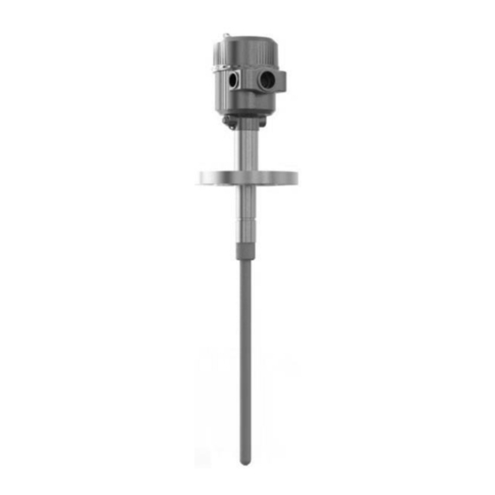
Components The PM 1 consists of the following main elements: ① Electronics Module ② Electronics Enclosure ③ Process Mount ④ Sensing Probe PM 1 Installation and Operating Manual v1.2 FilterSense © 2016... -
Page 10: Technical Data
NEMA 4/IP 66 Aluminum, Powder Coated Area Classification Ordinary/General Purpose Only, CE Approved (CSA/UL Approval Pending) Optional Hazardous Location, CSA Approved, Class II, Division II, Groups E- G, ATEX, IECEx (Approval Pending) PM 1 Installation and Operating Manual v1.2 FilterSense © 2016... - Page 11 Process Temperature -T12 -13F to +250F (-25C to +121C) Max. Operating Range -T14 -13F to +450F (-25C to +232C) Max. Process Pressure Full Vacuum to 10PSI (0.69 Bar) Max. Operating Range PM 1 Installation and Operating Manual v1.2 FilterSense © 2016...
-
Page 12: Model Configuration
Fully Insulated Probe (Teflon Coating) Enclosure NEMA 4/IP 66 Aluminum, Powder Coated Area Classification Ordinary/General Purpose Only, (Approval Pending), CE Mark Hazardous Location, Class II, Division II, Groups E-G, CSA/FM, ATEX, IECEx (Approval Pending) PM 1 Installation and Operating Manual v1.2 FilterSense © 2016... -
Page 13: Installation
③ Straight runs and laminar flow best for measurement. ④ Short straight runs are acceptable for basic leak detection. ⑤ Accessible negative pressure locations may be ③ ⑤ preferred to prevent exposure to toxic gases and particulate. PM 1 Installation and Operating Manual v1.2 FilterSense © 2016... - Page 14 ① Follow straight run considerations. Horizontal Pipes/Ducts Side or top mount recommended. Bottom mount not recommended. Proper mount and installation location will prevent buildup. PM 1 Installation and Operating Manual v1.2 FilterSense © 2016...
-
Page 15: Process Mounts
② Threaded Half-Coupling Process Mount ① ② Quick-Clamp -Clamp Allows quick and easy removal from process Allows rotation to easily align ① Quick-Clamp Nipple ② Quick-Clamp Process Mount ① ② PM 1 Installation and Operating Manual v1.2 FilterSense © 2016... -
Page 16: Mounting
0.125 in (3.175 mm) to 0.5 in (12.7 mm). ② Do not face weld. Weld center duct/pipe, perpendicular to the flow. Threaded Air and water tight seal. ② ① PM 1 Installation and Operating Manual v1.2 FilterSense © 2016... - Page 17 Do not use non-stainless steel mounts that ① may corrode and cause corrosive residue to ③ drip on the sensor. ② PM 1 Installation and Operating Manual v1.2 FilterSense © 2016...
-
Page 18: Test Port
If the test port must be located at an inaccessible location, a length of tubing can be used to improve access. Typical test port is a with a cap or shutoff valve. PM 1 Installation and Operating Manual v1.2 FilterSense © 2016... -
Page 19: Wiring
Recommended service loop is 1 to 2 times the sensor probe length. Service loop should extend downward to prevent moisture from entering enclosure. PM 1 Installation and Operating Manual v1.2 FilterSense © 2016... - Page 20 The ground cable must remain attached when the sensor is temporarily removed from the process. Do not disconnect the ground cable. PM 1 Installation and Operating Manual v1.2 FilterSense © 2016...
-
Page 21: Terminal Connections
PM 1-A Terminal connections for power and two alarm relays. All wiring must be rated for 250V minimum. Always disconnect power before connecting/ removing wiring from terminal connectors. PM 1 Installation and Operating Manual v1.2 FilterSense © 2016... - Page 22 Analog 4-20mA wire should be 22 AWG stranded shielded twisted pair, Belden 88761 or equivalent. Analog wiring cable shield should be terminated to earth ground in PLC/DCS panel/cabinet (terminate one end only). PM 1 Installation and Operating Manual v1.2 FilterSense © 2016...
-
Page 23: Operation
Status LEDs (PM 1-A Only) State Meaning Alarm 1 active Alarm 1 inactive Alarm 2 active Alarm 2 inactive Green Power No power PM 1 Installation and Operating Manual v1.2 FilterSense © 2016... -
Page 24: Settings
Operator View live process readings and all settings, no changes allowed. Engineer View and change all settings. Numeric Entry Next Enter 123456 123456 223456 123456 Exit & Accept Numeric Entry PM 1 Installation and Operating Manual v1.2 FilterSense © 2016... - Page 25 SECONDS NUMERIC ENTRY Language Selection LANGUAGE ENGLISH / DEUTSCH / FRANCAIS / ESPANOL PM 1 Information INFO SERIAL NUMBER / FIRMWARE VERSION / HARDWARE VERSION EXIT Exit Settings Exit Settings PM 1 Installation and Operating Manual v1.2 FilterSense © 2016...
- Page 26 SECONDS NUMERIC ENTRY Language Selection LANGUAGE ENGLISH / DEUTSCH / FRANCAIS / ESPANOL PM 1 Information INFO SERIAL NUMBER / FIRMWARE VERSION / HARDWARE VERSION EXIT Exit Settings Exit Settings PM 1 Installation and Operating Manual v1.2 FilterSense © 2016...
-
Page 27: Commissioning
Adjusting too low may result in an output that is too dynamic to easily interpret. Smoothing Seconds example. Actual response is application dependent. Setting Default Notes Smoothing Seconds Signal smoothing. Increase for smoother reading, decrease for more dynamic. PM 1 Installation and Operating Manual v1.2 FilterSense © 2016... -
Page 28: Alarms (Pm 1-A)
Setpoint continuously for a period longer than the Alarm Delay. LO Alarm Logic is used for loss of flow applications. Fail-Safe Relay State Fail-Safe Mode Power Off/Removed Normal Operation Active Alarm Normal (No) Open Open Closed Fail-Safe (Yes) Open Closed Open PM 1 Installation and Operating Manual v1.2 FilterSense © 2016... -
Page 29: Analog Output (Pm 1-T)
(4) cycles (5 minutes 30 seconds) or can be stopped before completion by setting Forcing mA to No. Once simulation has ended, the analog output will continue with normal operation. PM 1 Installation and Operating Manual v1.2 FilterSense © 2016... -
Page 30: Alarm Setpoint Guidance
Set a HI (increased powder flow) alarm above the desired powder flow rate. Set a LO (loss of powder flow) alarm below the desired powder flow rate. PM 1 Installation and Operating Manual v1.2 FilterSense © 2016... - Page 31 Peaks (After Cleaning Cycles) Filter Condition 1 to 10pA Less than 50pA No significant leaks 10 to 100pA 50 to 500pA Onset of leaks 100 to 1000pA 500 to 5000pA Significant leaks present PM 1 Installation and Operating Manual v1.2 FilterSense © 2016...
-
Page 32: Functional Verification
Shut down the process and fan. Ensure process flow has completely stopped. The slightest amount of flowing particles can create a signal. Monitor the particulate reading for a system zero. PM 1 Installation and Operating Manual v1.2 FilterSense © 2016... -
Page 33: Response Testing
Factory Testing Contact FilterSense to request an RMA in order to return the device for full factory testing. NIST traceable calibration certificates are available on request. The following parts can be returned for calibration: PM 1 (Electronics Module) PM 1 (Electronics Module &... -
Page 34: Troubleshooting
Check continuity across relay output circuit. Analog Output Not Use a multimeter in series to verify that the milliamps match the milliamp Responding measurement on the digital readout. Force the analog output. PM 1 Installation and Operating Manual v1.2 FilterSense © 2016... -
Page 35: Maintenance
Fully insulated probes are recommended for processes with moisture and most conductive particulates. Inspect the inside of the process mount for buildup and/or moisture. Check the outputs. Perform Functional Verification checks. PM 1 Installation and Operating Manual v1.2 FilterSense © 2016... -
Page 36: Spare Parts
Remove the two 9/64" hex screws that connect the electronics module to the enclosure. Remove the electronics module from the enclosure and replace with spare electronics module. Follow the above steps in reverse to complete the replacement. PM 1 Installation and Operating Manual v1.2 FilterSense © 2016...
Need help?
Do you have a question about the DynaCHARGE PM 1 Series and is the answer not in the manual?
Questions and answers