Table of Contents
Advertisement
Quick Links
Advertisement
Table of Contents

Summary of Contents for WarmTouch WT-5300A
- Page 1 Model WT-5300A Patient Warming System Operator’s Manual...
- Page 2 © 2010 Nellcor Puritan Bennett LLC. All rights reserved. To obtain warranty information contact your local Nellcor representative.
-
Page 3: Table Of Contents
Power Supply Cord..................21 Main Power ....................21 Temperature Control .................. 22 Air Filter....................... 23 Self-Supporting Air Hose ................23 Using WarmTouch™ CareQuilt™ and CareDrape™ Blankets ....23 Routine Maintenance ..................25 Overview...................... 25 Cleaning the Warming System..............25 Routine Maintenance ................. 25... - Page 4 Specifications ....................27 Overview...................... 27 Warming System Specifications ..............27 Transport and Shipping in Shipping Container ........28 Compliance....................28 Manufacturer’s Declaration ..............29 Electromagnetic Compatibility (EMC)..........29 Operator’s Manual...
-
Page 5: Safety Information
Overview Safety Information Overview This manual contains information for using the WarmTouch™ Model WT-5300A patient warming system. Before operating the warming system, thoroughly read the Operator's Manual. The latest version of this manual is available on the Internet at: http://www.nellcor.com/serv/manuals.aspx... -
Page 6: Warnings
If a malfunction occurs in the warming system, discontinue use. Notify your sales/service center of the malfunction. The unit must be serviced by an authorized service technician. WARNING No free-hosing. Keep hose nozzle connected to a WarmTouch™ blanket at all times or thermal injury may occur. Operator’s Manual... -
Page 7: Cautions
Safety Information WARNING WarmTouch™ CareDrape™ and CareQuilt™ blankets are for single patient use only. WARNING The warming system should not be operated in the presence of electromagnetic fields that are greater than 3 volts/meter. This could cause shutdown of the warming system by the fail-safe function within the equipment. - Page 8 Safety Information Caution The warming system is fitted with an air filter; however, airborne contamination should be considered when using the warming system. Caution If the warming system is mounted on the intravenous (IV) pole, it should be installed with the top of the unit’s handle less than 76 cm (30 inches) above the floor to prevent the IV pole from tipping over.
-
Page 9: Introduction
Overview Introduction Overview This chapter provides an introduction to the WarmTouch™ Model WT-5300A patient warming system. Intended Use The WarmTouch™ Model WT-5300A patient warming system (warming unit and blanket) is intended for prevention and treatment of hypothermia. For example, with the surgical patient, the patient in the preoperative holding area, the pregnant woman who shivers during epidural anesthesia due to hypothermia, or any patient who is uncomfortable in the cold critical care environment. -
Page 10: Safety Features
Introduction In creating this warm customized pocket of air around the hypothermic patient, it is important to note that stagnant air, even if it is warm, does not work as an effective heat transfer medium. Stagnant air acts as an insulator, preventing the boundary layer of molecules next to the skin surface from transferring heat. -
Page 11: Alarms
A yellow warning light illuminates whenever the control system identifies an over-temperature condition. Alarms The WarmTouch control circuit manages and monitors operation of the patient warming system. Should the control circuit encounter a failure condition, it reports failures using both visual and audible alarms. The visual alarm is a... -
Page 12: Hepa Filter
Introduction HEPA Filter Caution The HEPA filter must be changed every 2,000 hours of operation. Refer to the Routine Maintenance section in the Service Manual for replacement procedures requiring a qualified technician. The system's High Efficiency Particulate Air Filter is 99.97% efficient at 0.3-micron particle size. -
Page 13: Symbols
Symbols Symbols The symbols identified are symbols used on the warming system and warming system labeling. Table 1. Symbols on the Warming Unit Attention symbol, consult accompanying documentation Do not direct air from the hose to the patient (free-hosing); use hose only with warming blankets. -
Page 14: Description Of The Warming System
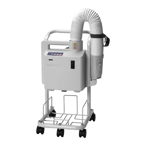
Introduction Table 2. Symbols on the Warming Unit Shipping Label Keep away from sunlight Keep upright, this side up Fragile Keep dry Relative humidity limitations: 15% to 95% ° ° Temperature limitations: -40 C to +70 Serial Number Reference Code Description of the Warming System The warming system CareQuilt™... - Page 15 Description of the Warming System Figure 2. Front View — Hose — Power Cord — Main Power Switch — Hour Meter — Nozzle — Control Panel Figure 3. Control Panel Warning Indicator and Temperature Selection Keys Operator’s Manual...
- Page 16 Introduction Figure 4. Back View 1 — Over-Temperature Test Port 5 — Filter Cover 2 — Instruction Label 6 — Bed Hook Bracket 3 — Blower Cart Clamp 7 — Nozzle Strap with Clip 4 — Warning Label Operator’s Manual...
-
Page 17: Installation
Overview Installation Overview This chapter contains information for installing the WarmTouch™ Model WT-5300A patient warming system. Operator’s Manual... -
Page 18: Cart Installation
Installation Cart Installation The warming system is shipped installed on the warming system cart. Ensure the three blower cart clamps are tight. Figure 5. Maximum Mounted Height Operator’s Manual... -
Page 19: Iv Pole Installation
IV Pole Installation IV Pole Installation The warming system should not be installed on the IV pole with the handle higher than 76 centimeters (30 inches). Figure 6. Maximum IV Pole Installation Height Operator’s Manual... -
Page 20: Patient Bed Installation
Installation Patient Bed Installation The patient rail connectors will fit on bed rails up to 1.4 inches (3.6 centimeters) wide. Figure 7. Bed Rail Installation Operator’s Manual... -
Page 21: Using The Warming System
Plug the warming system power cord into a hospital grade or suitable mains outlet. Main Power WARNING No free-hosing. Keep hose nozzle connected to a WarmTouch™ blanket at all times or thermal injury may occur. WARNING Thermal injury may occur if the warming system hose comes into contact with the patient. -
Page 22: Temperature Control
Using the Warming System Figure 8. Low Temperature Light Temperature Control WARNING The patient must be closely monitored for rewarming. Vasodilation and possible hypotension can occur. Use good judgment when selecting a temperature. If unsure of proper setting, consult with the attending physician. -
Page 23: Air Filter
Using WarmTouch™ CareQuilt™ and CareDrape™ Blankets WarmTouch™ CareQuilt™ and CareDrape™ blankets come in a range of sizes and configurations to fit patient individual sizes, surgical procedures, and comfort needs. Follow the instructions provided with all WarmTouch™ blankets for specific information concerning their recommended use. - Page 24 Using the Warming System Page Left Intentionally Blank Operator’s Manual...
-
Page 25: Routine Maintenance
Routine Maintenance Overview This chapter describes the steps required to maintain, service, and properly clean the WarmTouch™ Model WT-5300A patient warming system. Cleaning the Warming System Caution Do not spray, pour, or spill any liquid on the warming system, its accessories, connectors, switches, or openings in the case. - Page 26 Routine Maintenance Page Left Intentionally Blank Operator’s Manual...
-
Page 27: Specifications
Overview Specifications Overview This chapter contains physical and operational specifications for the WarmTouch™ Model WT-5300A patient warming system. Warming System Specifications Table 3. System Specifications Warming Blanket Specifications ° Maximum blanket surface temperature Blower Specifications Dimensions 38 cm x 41 cm x 28 cm... -
Page 28: Transport And Shipping In Shipping Container
Specifications Transport and Shipping in Shipping Container Table 4. Shipping Container Specifications Temperature: -40ºC to 70ºC (-40ºF to 158ºF) Altitude: -390 m to 6,096 m (-1,280 ft to 20,000 ft) Barometric Pressure: 1,060 hPa to 500 hPa (375 mmHg to 795 mmHg) Relative Humidity: 15% to 95% (non-condensing) Compliance... -
Page 29: Manufacturer's Declaration
Compliance Manufacturer’s Declaration WARNING The use of accessories and cables other than those specified may result in increased emission and/or decreased immunity of the warming system. The warming system is suitable for use in the specified electromagnetic environment. The customer and/or user of the warming system should ensure it is used in the prescribed electromagnetic environment. - Page 30 Specifications Electromagnetic Immunity These guidelines may not apply in all situations. Electromagnetic propagation is affected by absorption and reflection from structures, objects, and people. Table 7. Electromagnetic Immunity Guidelines EN 60601-1-2 Compliance Electromagnetic Environment Immunity Test Test Level Level Guidance Electrostatic ±6 kV contact ±6 kV contact Floor should be wood, concrete, or discharge (ESD)
- Page 31 Compliance For transmitters rated at a maximum output power not listed, estimate the separation distance using the equation in the corresponding column, where P is the maximum output [power rating of the transmitter in watts (W)] according to the transmitter manufacturer. Note: Portable and mobile RF communications equipment should be used no closer to any part of the warming system, including cables, than the recommended separation...
- Page 32 Specifications Page Left Intentionally Blank Operator’s Manual...
- Page 33 I n d e x , 23 , 21 Air filter Main power , 23 , 29 Air hose Manufacturer’s declaration , 10 Automatic temperature shutdown MRI warning , 20 , 20 Bed rail installation Patient bed installation Burn hazard Patient burns Possible explosion hazard , 21...
- Page 34 Page Left Intentionally Blank Operator’s Manual...
- Page 36 Tyco Healthcare Group LP Nellcor Puritan Bennett LLC 4280 Hacienda Drive Pleasanton, CA 94588 USA Toll Free: 1.800.635.5267 © 2010 Nellcor Puritan Bennett LLC All rights reserved. Manufactured in the U.S.A. 10064187 Rev B 09/2010...