Table of Contents
Advertisement
Quick Links
AVERTISSEMENT
WARNING
Assurez-vous de bien suivre les instructions données
If the information in these instructions is not followed
exactly, a fire or explosion could result causing
dans cette notice pour réduire au minimum le
risque d'incendie ou d'explosion ou pour éviter tout
property damage, personal injury, or death.
dommage matériel, toute blessure ou la mort.
— Do not store or use gasoline or other flammable
— Ne pas entreposer ni utiliser d'essence ou
vapors and liquids in the vicinity of this or any
ni d'autres vapeurs ou liquides inflammables
other appliance.
à proximité de cet appareil ou de tout autre
appareil.
WHAT TO DO IF YOU SMELL GAS
QUE FAIRE SI VOUS SENTEZ UNE ODEUR DE GAZ
Do not try to light any appliance.
•
Ne pas tenter d'allumer d'appareil.
•
•
Do not touch any electrical switch; do not use
•
Ne touchez à aucun interrupteur; ne pas vous
any phone in your building.
servir
•
Immediately call your gas supplier from a
le bâtiment.
neighbor's phone. Follow the gas supplier's
Appelez immédiatement votre fournisseur de gaz
•
instructions.
depuis un voisin. Suivez les instructions
du fournisseur.
If you cannot reach your gas supplier, call the
•
Si vous ne pouvez rejoindre le fournisseur,
fire department.
•
appelez le service des incendies.
— Installation and service must be performed by
— L'installation et l'entretien doivent être assurés
a qualified installer, service agency, or the gas
par un installateur ou un service d'entretien
supplier.
qualifié ou par le fournisseur de gaz.
des
téléphones
se
trouvant
dans
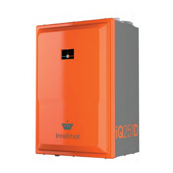
Operation & Installation Manual
iQ251D, Gen II
Advertisement
Table of Contents
Troubleshooting

Related Manuals for lntellihot iQ251D II


Summary of Contents for lntellihot iQ251D II
- Page 1 AVERTISSEMENT WARNING Assurez-vous de bien suivre les instructions données If the information in these instructions is not followed exactly, a fire or explosion could result causing dans cette notice pour réduire au minimum le risque d’incendie ou d’explosion ou pour éviter tout property damage, personal injury, or death.
- Page 2 Innovation is our hallmark and simplicity, effi ciency, and durability are at the core of every lntellihot product. Our products are proudly engineered and built in Galesburg, Illinois. lntellihot has helped commercial customers throughout the nation save thousands of dollars while eliminating downtime.
-
Page 3: Table Of Contents
Table of Contents 1. General Information 8. Water Connections Items Shipped With Water Heater..5 Quick Reference Installation Instructions . . . 28 Serial Number Plate Locations ... . 5 Hot Water Connection . - Page 4 AVERTISSEMENT WARNING Assurez-vous de bien suivre les instructions données If the information in these instructions is not followed dans cette notice pour réduire au minimum le exactly, a fire or explosion could result causing risque d’incendie ou d’explosion ou pour éviter tout property damage, personal injury, or death.
-
Page 5: General Information
1. General Information 1.1 Items Shipped With Water Heater 1.2 Serial Number Plate Locations The following items are shipped with the water heater. The unit’s serial number is located on the rating plate on the side panel of the unit. Please provide this serial number when inquiring about service or warranty solutions. -
Page 6: Safety
2. Safety 2.1 Safety Signal Words DANGER DANGER A. This water heater does not have a pilot. It is equipped with an ignition device which automatically lights the Indicates an imminently hazardous situation which, if burner. Do not try to light the burner manually. not avoided, will result in death or serious injury. - Page 7 WARNING (continued) Protect against snow and debris accumulation around the vent terminations. Regularly inspect the exhaust vent pipe and the air intake pipe to ensure they remain clear from obstructions at all times. CAUTION Make sure you know the location of the gas shut-off valve and how to operate it.
-
Page 8: Technical Speci� Cations
3. Technical Specifications 3.1 Specifications Chart iQ251D Series Gen II Specifications Technical Data Specification Type Indoor/Outdoor, Wall Hung, Fully Condensing, On-demand Water Heater Fuel Preset for natural gas but convertible to propane Minimum / Maximum Input (BTUs/hour) 30,000 / 251,000 Thermal Efficiency Dimensions H X W X D (inches) 26.4 X 17.8 X 15 (3.9 cu. -
Page 9: Clearance Requirements
3.3 Clearance Requirements In order for the water heater to operate properly and efficiently, the clearances specified in the table are required. Required Recommended Location From From Non- Service Combustibles Combustibles Clearance 6” (15.2 cm) 2” (50.8 cm) 12” (30.4 cm) Back 5/8”... -
Page 10: Dimensional Speci� Cations
3.6 Dimensional Specifications 15.0 [380] iQ251D Technical Specifications April 2021 - Revision 02... -
Page 11: Preparation Before Installation
4. Preparation Before Installation 4.1 Selecting an Indoor Installation Site 3. Locate the unit close to a drain and near gas and water connections. Note: When installing the water heater, follow all local building codes and the current edition of the National The water heater produces a significant amount of Fuel Gas Code (ANSI Z223.1/NFPA 54) in the USA, condensate during normal operation and should be... -
Page 12: Selecting An Outdoor Installation Site
4.2 Selecting an Outdoor Installation Site 2. Locate the unit close to a drain and near gas and water connections. Note: When installing the water heater, follow all local building codes and the current edition of the National The water heater produces a significant amount of Fuel Gas Code (ANSI Z223.1/NFPA 54) in the USA, condensate during normal operation and should be located or National Gas and Propane Installation Code (CAN/... -
Page 13: Wall Mounting
5. Wall Mounting 5.1 Mounting the Unit to the Wall 2. With assistance, hang the unit’s interlocking bracket (1) onto wall bracket (2). All water heaters come with an upper mounting bracket with 3. Loosen the four mounting screws in the lower bracket, predrilled holes spaced on 16 inch centers to facilitate easy and slide it against the wall to create a 5/8”... -
Page 14: Gas Connection
6. Gas Connection Natural Gas Static Gas Pressure WARNING Parameters Specifications FIRE AND/OR EXPLOSION HAZARD Minimum Static Gas Pressure 1/2” To avoid serious injury or even death, the gas pipe 6” W.C. (black iron pipe) installation and the gas pipe inlet pressure test must be Minimum Static Gas Pressure 3/4”... -
Page 15: Gas Piping Material
b. The total straight length of gas pipe, as well as the 6.8 Gas Pipe Drip Leg and Shut-off Valve additional length for any elbows, must be considered 1. Install a shut-off valve. Local codes may require multiple when sizing the gas pipe. Total equivalent length should units to have a shut-off valve on the main gas supply pipe be calculated from the meter or source location to the and one on each unit. -
Page 16: Gas Pipe Sizing Tables
6.9 Gas Pipe Sizing Tables This information is for reference only. Refer to gas pipe manufacturer specifications for actual delivery capacity. Contact the local gas supplier for actual BTU/ft rating. This data has been copied from the National Fire Protection Association Article 54 (NFPA 54). - Page 17 Pipe sizes and BTU/h capacity (PROPANE). Use this table for static gas pressure GREATER THAN 5” W.C. Length 1/2" 3⁄4" 1" 1-1/4" 1-1/2" 2" 2-1/2" 3" 4" including fittings (feet) 409,000 608,000 1,150,000 2,350,000 3,520,000 6,790,000 10,800,000 19,100,000 39,000,000 289,000 418,000 787,000 1,620,000...
-
Page 18: Air Intake Inlet And Exhaust Gas Outlet Pipe Connections
7. Air Intake Inlet and Exhaust Gas Outlet Pipe Connections 3. Determine the straight pipe distance and the number of DANGER elbows required to route the air intake inlet and exhaust gas outlet pipes to their termination point. Improper venting of the water heater “7.6 Intake Air Inlet and Exhaust Gas Outlet Pipe Diameter will result in excessive levels of carbon and Length”... -
Page 19: Two Pipe Vent System (Direct Vent)
7.3 Two Pipe Vent System (Direct Vent) SAFETY INSTRUCTIONS 7.3.1 Single Unit Configurations On multiple unit installations, the air intake inlet and The water heater can be directly vented without any exhaust gas outlet pipe from each water heater must be modification using a three inch diameter pipe. -
Page 20: Multiple Units Con� Gurations
7.3.2 Multiple Units Configurations 7.3.3 Side Wall Air Intake Inlet and Exhaust Gas Outlet Pipe Termination When more than one unit is installed, refer to “7.6 Intake Air Inlet and Exhaust Gas Outlet Pipe Diameter and Length” on 1. Terminate the air intake inlet pipe with a 90° elbow page 24. -
Page 21: Roof Air Intake Inlet And Exhaust Gas Outlet Pipe Termination
7.3.4 Roof Air Intake Inlet and Exhaust Gas Outlet 7.4 Single Pipe Venting System (Power Vent) Pipe Termination 7.4.1 Single Unit Venting the unit through the roof is also an option. With this The following illustrations represent some typical power installation method, the terminations must extend at least 12”... -
Page 22: Multiple Units
7.4.2 Multiple Units 7.4.3 Concentric Venting Termination (Single Unit) When installing multiple units, refer to “7.6 Intake Air Inlet and Exhaust Gas Outlet Pipe Diameter and Length” on page If desired, an optional concentric venting system, which uses one 5” opening through an exterior wall or roof, can be used, as opposed to cutting two 3”... -
Page 23: Concentric Venting Termination (Multiple Units)
7.4.4 Concentric Venting Termination (Multiple Units) In order to conform to some national codes, when two or more water heaters are installed they must be individually vented. When two or more units are vented near each other, each vent termination must be installed, as shown, to avoid recirculation of flue gases. -
Page 24: Intake Air Requirements
7.5 Intake Air Requirements SAFETY INSTRUCTIONS When using the single exhaust gas outlet pipe or power vent Do not operate the unit in an area that will draw in outside method, the following table outlines the required opening air contaminated with high levels of dust, sawdust, sizes for the intake air coming into the room and the required aerosols, such as paint, or other airborne contaminants. -
Page 25: Venting Clearance Speci� Cations
7.7 Venting Clearance Specifications Operable Fixed Closed Fixed Closed Operable Inside Corner Detail Air Inside Inlet Vent Terminal Gas Meter/Regulator IQ-010 Area Where Terminal is Not Permitted Venting Clearance Specifications Clearance Distance Item Description Canada Clearances above grade, veranda, porch, deck, or balcony 1 foot 1 foot Clearances to window or door that may be opened... -
Page 26: Exhaust Gas Outlet Pipe Materials
7.8 Exhaust Gas Outlet Pipe Materials If the inlet/return water temperature will exceed 150°F (66°C), do not use PVC pipe. Follow the display prompts SAFETY to set the maximum water temperature for the exhaust gas INSTRUCTIONS outlet pipe material being used. For Canadian installations, plastic exhaust gas outlet piping must comply with CAN/CGA B149.1 and be certified to the Standard For Type BH Gas Venting... -
Page 27: Recommended Exhaust Gas Outlet Pipe Transitions
7.10 Recommended Exhaust Gas Outlet Pipe Transitions Do not use 90 degree transition into a reducer or a straight pipe. Do not use 90 degree t-fitting for exhaust gas outlet. 1/4” Rise Per Foot Run Condensate Drain 3X DIA. MIN 45°... -
Page 28: Water Connections
8. Water Connections Note: If the flow rate changes faster than ten GPM in one second, an error message will appear and a water hammer arrester must be installed to prevent damage to the water heater. 8.1 Quick Reference Installation Instructions 1. -
Page 29: Cold Water Connection
7. To conserve energy, insulate all hot water pipes and 4. Connect the unit to the existing cold water pipes. recirculation pipes. If the existing plumbing is 1/2” pipe, adapters may be used to transition from the 3/4” pipe. SAFETY 5. - Page 30 3. Route the drain line to nearby floor drain, neutralizer, or condensate pump. a. If a floor drain is used to remove the discharge, route the drain hose over or into the drain. b. Long drain lines should contain a union to facilitate servicing the unit or cleaning the drain line.
-
Page 31: External Recirculation Options
8.5 External Recirculation The following illustrations provide possible external recirculation options. Recirculation is required for system to function properly. Hot Water Return Recirculation Line HOT WATER FIXTURES Cold Water Supply Gas Supply Hot Water Supply Expansion Tank "RESTAURANT" OPTION WITH NO BUILDING RECIRCULATION HOT WATER FIXTURES Cold Water Supply... - Page 32 MIXING VALVE OPTION Low Temp Return Recirculation Line High Temp Return Cold Water Supply Mixing Valve* Recirculation Line LOW TEMP FIXTURES HIGH TEMP FIXTURES Gas Supply Expansion Hot Water Supply Tank * PLEASE FOLLOW MIXING VALVE MANUFACTURER GUIDELINES. iQ251D Water Connections May 2018 - Revision 01...
-
Page 33: Electrical
9. Electrical 9.2 Electrical Connection and Polarity WARNING On single unit installations, make sure the electrical outlet being used is wired with at least 12 gauge wire and grounded. To avoid serious injury or even death, follow all A GFI ground fault receptacle is recommended. Only one applicable local, state, and national regulations, water heater should be plugged into an outlet with the 12 mandates, and building codes for guidelines to... -
Page 34: Adjusting Co2 Level
10. Adjusting CO Level 10.1 General Information 10.2 Adjustment Procedure 1. Remove the front cover panel. This procedure is required: 1) only during installation in a high-altitude location over 2. Locate the gas valve on the heat engine. 8,000 feet, or 2) when converting the unit from natural gas to propane. - Page 35 4. Follow the display screens. NOTICE Do NOT change the blower speed settings. This adjustment MUST be performed by factory personnel ONLY. Changing this setting WILL VOID the warranty! 5. Create a hot water flow of at least 6.0 GPM, as shown on the display screen.
- Page 36 8. Record “initial output” in Hire Fire Recorded Values table. 12. Record “initial output” in Low Fire Recorded Values table. 9. If the CO values are within appropriate range, proceed to and CO Standards Step 10; otherwise, continue. Description Range Max.
-
Page 37: Natural Gas To Propane Conversion
11. Natural Gas to Propane Conversion b. Place the circuit breaker for the water heater at the main electrical panel in the OFF position. Verify there SAFETY INSTRUCTIONS is no power to the unit(s). A qualified service technician MUST make the required changes to convert the water heater from Natural Gas to Propane. - Page 38 2. Follow the display screens to make sure if the unit is now set to propane. PROPANE Verify unit is now set to PROPANE. 3. Refer to section “10. Adjusting CO Level” on page 34 in this manual for instructions to adjust CO levels.
-
Page 39: Operation
12. Operation 12.1 Control Panel 12.2 Turning Water Heater ON and OFF 1. When the power cord is plugged in the Main Menu screen will automatically appear. 2. To turn the water heater OFF, press and hold the Power button in the upper left of the screen. 3. -
Page 40: Setting The Time
12.3 Setting the Time 12.4 Adjusting the Water Temperature Note: The outlet water temperature is factory preset to 120°F; however, these commercial water heaters are capable of heating water to 190°F. DANGER Hot water temperature over 125°F (52°C) can instantly cause severe burns or death from scalding. -
Page 41: Security
12.5 Security 12.5.2 Forgot Passcode If the unit passcode is lost or forgotten, press the “?” icon on 12.5.1 Setting Passcode Protection the screen which opens the technical support screen. Call to It is not necessary to set a passcode for the water heater to obtain the passcode. -
Page 42: Life Screen
12.7 Life Screen Service Alert Reset Code Electrode 0836 These screens provide a visual indication of the remaining life of various components. Blower 2009 0721 Time Valve (Water Valve) Note: Parts can be ordered by contacting technical support. Gas Valve 0682 O-Ring 0310... -
Page 43: More Screens
12.9 More Screens Commercial Status of Wi-Fi connection screen. 12.9.2 Error History 12.9.1 Wi-Fi Intellihot Gen II water heaters are Wi-Fi capable with the factory installed IGT-SPR0085 WI-FI module. This feature also allows the units to be monitored and controlled from a mobile device. -
Page 44: Tellicare Service (Subscribe At Startup)
12.9.3 telliCare Service (Subscribe at Startup) telliCare is a Wi-Fi enabled, prognostics and predictive maintenance service for Gen II water heaters. This service allows water heaters to be monitored and controlled remotely via an app on a mobile device. Tap anywhere on the screen to continue. If setup is not complete: If telliCare setup is skipped, register the unit by scanning the QR Code via the App. - Page 45 Subscribe to this service by downloading the telliCare app from iTunes App Store and following the prompts on the app. iQ251D Operation May 2018 - Revision 01...
-
Page 46: Connecting Multiple Units
13. Connecting Multiple Units 13.1 General Information Multiple units can be connected together to supply large demands of hot water. The water heaters communicate through a cable connection between each water heater. The benefits of connecting the units are: • When demand for hot water is low, fewer units will operate. •... - Page 47 10. Remove the front cover and locate the main circuit 12. Using the supplied cables, connect one end of a cable board. into either of two jack receptacles (arrows) located on the circuit board and the other end to the jack in the 11.
-
Page 48: Tellicare For Multiple Units
13.2.1 telliCare for Multiple Units If cascading mulitple units, the Wi-Fi module on all units besides “Unit 1” in the sequence need to be disconnected to make room for cascade communication cables. Remove the attached cable at each end from the referenced jacks and set aside. -
Page 49: Maintenance
14. Maintenance 14.1 Draining the Water Heater 4. Remove the clip holding the pipe into the heat engine. Flex the pipe enough to allow the water to drain from the heat engine. CAUTION Hot water can cause burns to the skin. The water temperature is factory set to 120°F (49°C). -
Page 50: Wiring Diagrams And Troubleshooting
15. Wiring Diagrams and Troubleshooting 15.1 Operational Flow Chart IQ-35 iQ251D Wiring Diagrams and Troubleshooting May 2018 - Revision 01... -
Page 51: Complete Wiring Diagram (All Models)
15.2 Complete Wiring Diagram (all models) iQ251D Wiring Diagrams and Troubleshooting May 2018 - Revision 01... -
Page 52: Troubleshooting Guide
15.3 Troubleshooting Guide Description Possible Cause Remedy Blower Speed Fault • Blower noisy / impeller jammed. • Inspect blower / impeller. Clean and remove any obstructions. • Disconnected signal wire. • Check PWN signal. Check for loose wires / pins, and repair. •... - Page 53 Description Possible Cause Remedy Flue Temperature Exceeded Set Limit • Incorrect vent set up. • If vent pipe material is CPVC or polypropylene, ensure that CPVC is selected in the vent material screen. • High inlet temperature. • Ensure inlet temperature is lower than 150°F if vent pipe material is PVC or lower than 190°F if vent pipe material is CPVC or polypropylene.
- Page 54 Description Possible Cause Remedy System Alert • A system alert is present (main • Refer to the remedy for indicated part or system. menu screen). • Malfunction of monitored part or system. Fault • A fault or error is present (main •...
-
Page 60: Requirements For State Of Massachusetts
17. Requirements for State of Massachusetts 17.1 Notice Before Installation 3. SIGNAGE. A metal or plastic identification plate shall be permanently This appliance must be installed by a licensed plumber or gas mounted to the exterior of the building at a minimum fitter in accordance with the Massachusetts Plumbing and height of eight (8) feet above grade directly in line with Fuel Gas Code 248 CMR Sections 2.00 and 5.00. -
Page 61: Warranty
18. Warranty 18.1 Warranty Contaminant Level General Aluminum 0.05 to 0.2 mg/l This water heater is warranted by Intellihot, Inc., and Chloride 250 mg/l covers defects in materials and workmanship, subject to Color 15 color units the applicable time periods and terms below. This warranty Copper 1.0 mg/l begins on the date of commissioning. - Page 62 Not Covered by this Warranty • This warranty does not cover failures or problems due to: • Failure to install in accordance applicable building codes, ordinances, normal plumbing, or electrical trade practices. • Improper installation, improper use, improper maintenance, improperly made replacements or repairs, accidents, or abuse.
- Page 63 NOTES iQ251D Warranty May 2018 - Revision 01...
-
Page 64: Product Warranty
19. Product Warranty 19.1 Warranty To register via the telliCare app, refer to “12.9.3 telliCare Service (Subscribe at Startup)” on page 44. Warranty Registration Intellihot Inc. 2900 W. Main Street Galesburg, IL 61401 Or fill out the information in the form below and mail to the following address: Make a copy or cut here to remove page. - Page 65 iQ251D Product Warranty May 2018 - Revision 01...
- Page 66 NOTES iQ251D Product Warranty May 2018 - Revision 01...
- Page 67 NOTES iQ251D Product Warranty May 2018 - Revision 01...
- Page 68 iQ251D Product Warranty May 2018 - Revision 01...
- Page 69 Revised 04-2021 Part#: IGT-MNL0024 Endless Progress. ™ Intellihot Inc. | www.intellihot.com | 2900 W. Main Street, Galesburg, IL 61401 | 877.835.1705 | support@intellihot.com iQ251D Product Warranty May 2018 - Revision 01...