
Related Manuals for Noncontact meters NCM-603

Summary of Contents for Noncontact meters NCM-603
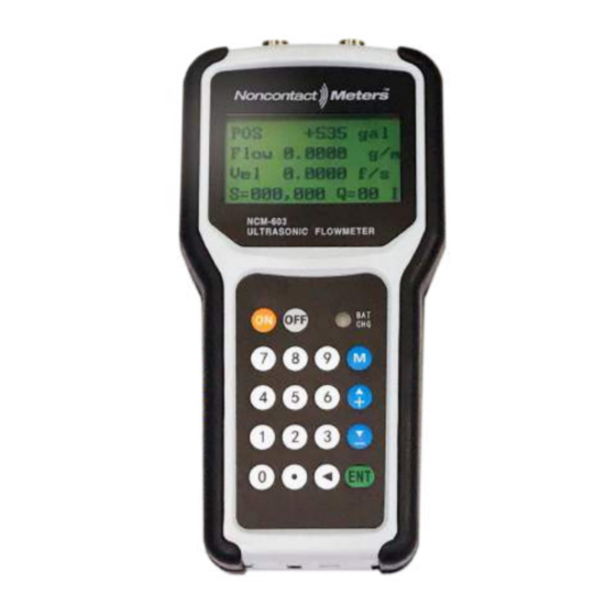
- Page 1 Portable Hand Held Transit Time Ultrasonic Flow Meters Clamp-On Meter User Manual NCM-603 O&M Rev 07/24/2021...
-
Page 2: Table Of Contents
Contents Quick Start Guide ..........................4 1. Introduction ............................ 7 1.1 Preface ..........................7 1.2 Features ..........................7 1.3 Principle of Measurement ....................8 1.4 Parts Identification ....................... 9 1.5 Typical Applications ......................11 ................................. 1.8 Specifications ........................12 2. Measurement ..........................13 2.1 Built-in Battery ........................ - Page 3 2.9.4 Transit Time Ratio ......................22 3. How To ............................23 3.1 How to check if the instrument works properly ..............23 3.2 How to check the liquid flowing direction ................. 23 3.3 How to change units systems ..................... 23 3.4 How to select a flow rate unit.....................
- Page 4 3.28 How to charge the built-in battery..................27 3.29 How to calibrate the flowmeter ..................27 4. Menu Window Details ........................28 ................................5.Troubleshooting ..........................33 5.1 Power-on Errors ........................33 5.2 Working Status Errors ......................33 5.3 Other Problems and Solutions .................... 34 6.
-
Page 5: Quick Start Guide
NCM-603 Handheld Ultrasonic Flow Meter Quick Start Step 1: Power on Charge the battery fully before using. Press the ON button. The meter will go through a self- check process. After a few seconds the screen will display information. Step 2: Program Flow Meter 2.1: Enter transducer info... - Page 6 Step 5: Display Flow Press M1 to return to the main screen that will display Total, Rate, Velocity, Signal Strength & Quality. Noncontact Meters Inc 755 Ash St, Canton GA 30114 – USA Ph (770)516-3999 sales@noncontactmeters.com www.noncontactmeters.com NCM-603 Quick Start Rev 7.29.21...
-
Page 7: Introduction
H battery can work continuously for more than 8 hours without recharge. The NCM-603 also has a built-in data-logger, which allows storage of 2,000 lines of data. The stored information can be downloaded to a PC through its RS232 connection port with software or Windows HyperTerminal software. -
Page 8: Principle Of Measurement
1.3 Principle of Measurement The NCM-603 ultrasonic flowmeter is designed to measure the velocity of liquid within a closed conduit. It uses the well-known transit-time technology. The transducers are a non- contacting, clamp-on type. They do not block the flow, thus there is no pressure drop. They are easy to install and remove. -
Page 9: Parts Identification
1.4 Parts Identification Top View Front View Bottom View NCM-603 Complete KIT with hard carrying case... - Page 10 Transducers: 28") M1-type (2”- Transducer Cable 5m x 2 AC/DC Power and Battery Charger Adapter RS232C Serial Cable...
-
Page 11: Typical Applications
1.5 Typical Applications The NCM-603 flow meter can be applied to a wide range of pipe flow measurements. The pipe size ranges from 1”-120” (20mm-3000mm). A variety of liquid applications can be accommodated: ultra-pure liquids, potable water, oil, chemicals, raw sewage, reclaimed water, cooling water, river water, sea water, plant effluent, etc. - Page 12 Output Optically isolated Open Collector Transistor output (OCT) for frequency and pulse. Recording Automatically records the daily total of the last 128 days, the monthly total of the last 64 months and the yearly total of the last 5years. Linearity 0.5% Repeatability 0.5%...
-
Page 13: Measurement
2. Measurement 2.1 Built-in Battery The instrument can operate either from the built-in Ni-H rechargeable battery, which will last over 8 hours of continuous operation when fully charged, or from an external AC/power supply from the battery charger. When the red LED is on, the battery is charging. The battery-charging circuit employs both constant-current and constant-voltage charging methods. -
Page 14: Keypad
display. When the user adjusts the position of the installed transducers, the flowmeter will re-adjust the signal gain automatically. Any user-entered configuration value will be stored in the NVRAM (non-volatile memory), until it is modified by the user. 2.3 Keypad The keypad of the flowmeter has 16+2 keys. -
Page 15: Menu Windows
There are three different types of menu windows: (1) Menu windows for number entering, e.g., M11 for setting up the pipe outer diameter. (2) Menu windows for option selection, e.g., M14 for the selection of pipe materials. (3) Results display windows, e.g. window M00 for displaying Velocity, Flow Rate, etc. For number entering windows, the user can directly press the digit keys if the user wants to modify the value. -
Page 16: Steps To Configure The Parameters
output. M+0~M+8 windows for some additional functions, including a scientific calculator, display of the total working time and display of the time and the flow rate when the device is turned on and turned off. Other menu windows such as M88 have no functions, or functions that were cancelled because they were not applied to this version of the software. -
Page 17: Transducers Mounting Allocation
(6) Press key ▼/- to enter into M23 window. Press ENT key to get into the option selection mode. Use keys ▲/+ and▼/- to scroll up and down to the proper transducer type, and then press ENT key. (7) Press key ▼/- to enter into M24 window. Press ENT key to get into the option selection mode. - Page 18 Select a relatively new straight pipe line if it is possible. Old pipe tends to have corrosions and depositions, which could affect the results. If you have to work on an old pipe, we recommend you to treat the corrosions and depositions as if they are part of the pipe wall or as part of the liner.
-
Page 19: Transducers Installation
2.8 Transducers Installation The transducers used by the NCM-603series ultrasonic flow meter are made of piezoelectric crystals both for transmitting and receiving ultrasonic signals through the wall of liquid piping system. The measurement is realized by measuring the traveling time difference of the ultrasonic signals. -
Page 20: Z-Method Installation
diameters ranging from 25mm (1”) to 400mm (16”). It is also called the reflective method. 2.8.3 Z-method Installation Z-method is commonly used when the pipe diameter is between 200mm (8”) and 3,000mm (120”). 2.8.4 W-method Installation W-method is usually used on plastic pipes with a diameter from 20mm (3/4”) to 50mm (2”). -
Page 21: Installation Checkup
2.8.5 N-method Installation This method is rarely used. 2.9 Installation Checkup After completion of the transducer installation, the user should check the following items: the receiving signal strength, the signal quality Q value, the delta time (traveling time difference between the upstream and the downstream signals), the estimated liquid sound speed, the transit time ratio, etc. -
Page 22: Total Transit Time And Delta Time
2.9.3 Total Transit Time and Delta Time The total transit time (or traveling time) and the delta time are displayed on menu window M93. They are the primary data for the instrument to calculate the flow rate. Therefore, the measured flow rate will vary as the total transit time and delta time vary. The total transit time should remain stable or vary in a very small range. -
Page 23: How To
3. How To 3.1 How to check if the instrument works properly Generally speaking, when ‘R’ is displayed in the lower right corner of the LCD display, the instrument is working properly. If an ‘H’ flashes instead, the received signal could be poor. Please refer to Chapter 5fortroubleshooting. -
Page 24: How To Restore The Factory Default Setups
3.8 How to restore the factory default setups Go to window M37.Press . key followed by the backspace key ◄ This operation will erase all the parameters entered by the user and setup the instrument with factory default values. 3.9 How to use the damper to stabilize the flow rate The damper acts as a filter for a stable reading. -
Page 25: How To Use The Built-In Data Logger
For no-password locking / unlocking, just press ENT key in window M47. If the password is forgotten, please contact the manufacturer. 3.14 How to use the built-in data logger The built-in data logger has a space of 24K bytes of memory, which will hold about 2000 lines of data. -
Page 26: How To Produce An Alarm Signal
0.1 cubic meter of liquid flow. Assume also that the pulse output is connected to an internal Buzzer. With every 0.1 cubic meter of flow, we need the BUZZER to beep for a while. In to achieve this, the following steps must be performed: Select the Cubic Meter (m ) unit in window M32. -
Page 27: How To Adjust The Lcd Contrast
modification. 3.21 How to adjust the LCD contrast Use M70 to adjust the LCD contrast. The adjusted results will be stored in the EEPROM so that the MASTER ERASE (factory default restoration) will make no effect on the contrast. 3.22 How to use the RS232 serial interface Use M62 for the setup of the RS-232C serial interface. -
Page 28: Menu Window Details
4. Menu Window Details Menu window Function Display POS (positive), NEG (negative) and NET (net) totalizer values. Display signal strength, signal quality and working status Display POS totalizer, instantaneous flow rate, velocity, signal strength, signal quality and working status Display NEG totalizer, instantaneous flow rate, velocity, signal strength, signal quality and working status Display NET totalizer, instantaneous flow rate, velocity, signal strength, signal quality and working status... - Page 29 Window for selecting fluid type For standard liquids (no need to enter liquid sound speed) include: (0) Water (1) Sea Water (2) Kerosene (3) Gasoline (4) Fuel oil (5) Crude Oil (6) Propane at -45°C (7) Butane at 0°C (8)Other liquids (9) Diesel Oil (10)Caster Oil (11)Peanut Oil (12) #90 Gasoline (13) #93 Gasoline (14) Alcohol (15) Hot water at 125°C Window for entering the sound speed of non-standard liquids...
- Page 30 Turn on or turn off the NEG totalizer (1) Totalizer reset (2) Restore the factory default settings. Press the dot key followed by the backspace key. Attention: it is recommended to make notes on the parameters before doing the restoration. Manual totalizer used for calibration.
- Page 31 each RH20 series flowmeter. The user can use the ESN for instrumentation management RS-232 setup. Baud rate can be 75 to 115,200 bps Not used Not used Not used Not used Window to set up the frequency range (lower limit and upper limit) for the frequency output.
- Page 32 entered pipe parameters are correct and the transducers are properly installed. Otherwise, the pipe parameters and the transducer installation should be checked. Display the estimated sound speed of the fluid in the pipe. If this value has an obvious difference with the actual fluid sound speed, the user is recommended to check if the pipe parameters are correct and if the transducer installation is good.
-
Page 33: Troubleshooting
5.Troubleshooting §5.1 Power-on Errors When powered on, the RH20 series ultrasonic flowmeter automatically starts the self-diagnosis process to find if there are any hardware and software problems. If a problem is identified, an error message will be displayed. The following table shows the possible error messages, the corresponding causes and their solutions. -
Page 34: Other Problems And Solutions
the pipe is too thick. (5)Transducer cables are not properly connected Hardware Error Hardware problem Contact the manufacturer PoorSig Detected (1)Poor signal detected (1)Adjust measuring location (2)Transducers installed (2)Polish the pipe surface and improperly clean the spot (3)Too much fouling (3)Make sure the couplant is (corrosion, deposition,... - Page 35 Incorrect transducer installation. Re-install the transducers carefully. The ‘Zero Point’ is wrong. Go to window M42 and redo the “Zero Point” setup. Make sure that the flow inside the pipe is standstill. No velocity is allowed during this setup process. Q: Why does the battery not work as long as the time indicated on M07? The battery may have come to the end of its service life.
-
Page 36: Serial Communication
6.2 Connect the Flow Meter to a PC A standard USB cable is provided with your NCM-603 unit. Just simply plug the cable to the flowmeter USB port on one end and to the computer on the other end. Then, turn on the flowmeter. -
Page 37: Communication Protocol
- 34 - Handheld Ultrasonic Flowmeter 6.5Communication Protocol The protocol is comprised of a set of basic commands that are strings in ASCII format, ending with a carriage (CR) and line feed (LF). Commonly used commands are listed in the following table. Command Function Data Format... -
Page 38: Protocol Prefix Usage
Handheld Ultrasonic Flowmeter - 35 - Command binder to make a longer & command by combining up to 6 commands Notes * CR stands for Carriage Return and LF for Line Feed. ‘d’ stands for a digit number of 0~9. *** @ stands for the key value, e.g., 30H for the value of ASCII key ‘0’. -
Page 39: The M Command And The Ascii Codes
- 36 - Handheld Ultrasonic Flowmeter 6.7The M command and the ASCII Codes The protocol provides the capability of virtual key-pressing. A remote RS-232C terminal can send an ‘M’ command along with a key code to simulate the scenario that the key is pressed through the keypad of the flowmeter. -
Page 40: Software Upgrade Service
- 38 - Handheld Ultrasonic Flowmeter as hazard-free device by a recognized organization, you are required to supply the certification for service. 3. If the return item does not have a RMA# associated, it will be sent back without any service conducted. -
Page 41: Appendix
Handheld Ultrasonic Flowmeter - 39 - 8. Appendix 8.1 Battery Maintenance and Replacement The battery is Ni-H rechargeable battery. Therefore, it is recommended to discharge the battery by leaving the instrument ON (it will automatically turn OFF after a few minutes) every 3 months. Recharge the battery again to its full extent with the supplied AC adapter. - Page 42 - 40 - Handheld Ultrasonic Flowmeter §8.2.2 Prepare the Pipe Surface Clean the pipe surface where the transducers will be mounted. Remove rust and paint. Sand the surface if not smooth. Use wet cloth to wipe off the powder after sanding. Dry up the surface.
- Page 43 Handheld Ultrasonic Flowmeter - 41 - Transducer Spacing for HS Transducer For pipe size 1”~1.5” metal pipe, we recommend you to put damping material, such as GraceIce, around the pipe surface. If wrapping acoustic damping material is not an option, try to put some acoustic couplant around the pipe to absorb acoustic noise.
-
Page 44: Pipe Size Tables
- 42 - Handheld Ultrasonic Flowmeter 8.3 Pipe Size Tables Table A1: Standard copper tubes according ASTM B88. Tolerance on Outside Wall Thickness Nominal Actual Outside Diameter (inches) Size Diameter (inches) (inches) (inches) Annealed Drawn Nominal Tolerance Type K 0.875 0.003 0.001 0.065... - Page 45 Handheld Ultrasonic Flowmeter Type M 0.875 0.003 0.001 0.032 0.003 1 1/8 1.125 0.0035 0.0015 0.035 0.004 1 1/4 1 3/8 1.375 0.004 0.0015 0.042 0.004 1 1/2 1 5/8 1.625 0.0045 0.002 0.049 0.005 2 1/8 2.125 0.005 0.002 0.058 0.006 2 1/2...
- Page 46 Handheld Ultrasonic Flow meter Table A2 (continued): Standard ANSI Pipe Size Data for Carbon Steel and Stainless Steel Pipe ANSI B 36.10 ANSI B 36.10 ANSI B 36.19 Nominal Outer Wall Carbon Steel Carbon Steel Stainless Steel Pipe Size Diameter Thickness Wall Schedule...
- Page 47 Handheld Ultrasonic Flowmeter Table A2 (continued): Standard ANSI Pipe Size Data for Carbon Steel and Stainless Steel Pipe ANSI B 36.10 ANSI B 36.10 ANSI B 36.19 Nominal Outer Wall Carbon Steel Carbon Steel Stainless Steel Pipe Size Diameter Thickness (in) (in) (in)
- Page 48 Handheld Ultrasonic Flowmeter Table A2 (continued): Standard ANSI Pipe Size Data for Carbon Steel and Stainless Steel Pipe ANSI B 36.10 ANSI B 36.10 ANSI B 36.19 Nominal Outer Wall Carbon Steel Carbon Steel Stainless Steel Pipe Size Diameter Thickness Wall Schedule Schedule...
- Page 49 Handheld Ultrasonic Flow meter Table A2 (continued): Standard ANSI Pipe Size Data for Carbon Steel and Stainless Steel Pipe ANSI B 36.10 ANSI B 36.10 ANSI B 36.19 Nominal Outer Wall Carbon Steel Carbon Steel Stainless Steel Pipe Size Diameter Thickness Wall Schedule...
- Page 50 Handheld Ultrasonic Flow meter Table A2 (continued): Standard ANSI Pipe Size Data for Carbon Steel and Stainless Steel Pipe ANSI B 36.10 ANSI B 36.10 ANSI B 36.19 Nominal Outer Wall Carbon Steel Carbon Steel Stainless Steel Pipe Size Diameter Thickness (in) (in)
- Page 51 Handheld Ultrasonic Flow meter Table A2 (continued): Standard ANSI Pipe Size Data for Carbon Steel and Stainless Steel Pipe ANSI B 36.10 ANSI B 36.10 ANSI B 36.19 Nominal Outer Wall Carbon Steel Carbon Steel Stainless Steel Pipe Size Diameter Thickness Wall Schedule...
- Page 52 Handheld Ultrasonic Flow meter Table A2 (continued): Standard ANSI Pipe Size Data for Carbon Steel and Stainless Steel Pipe ANSI B 36.10 ANSI B 36.10 ANSI B 36.19 Nominal Outer Wall Carbon Steel Carbon Steel Stainless Steel Pipe Size Diameter Thickness Wall Schedule...
- Page 53 Handheld Ultrasonic Flow meter Table A2 (continued): Standard ANSI Pipe Size Data for Carbon Steel and Stainless Steel Pipe ANSI B 36.10 ANSI B 36.10 ANSI B 36.19 Nominal Outer Wall Carbon Steel Carbon Steel Stainless Steel Pipe Size Diameter Thickness Wall Schedule...
- Page 54 Handheld Ultrasonic Flow meter Table A3: Standard Classes of Cast Iron Pipe Class A Class B Class C Class D Nominal Outer Wall Outer Wall Outer Wall Outer Wall Pipe Size Diameter Thickness Diameter Thickness Diameter Thickness Diameter Thickness (in.) (in.) (in.) (in.)
- Page 55 Handheld Ultrasonic Flow meter Table A3 (continued): Standard Classes of Cast Iron Pipe Class E Class F Class G Class H Nominal Outer Wall Outer Wall Outer Wall Outer Wall Pipe Size Diameter Thickness Diameter Thickness Diameter Thickness Diameter Thickness (in.) (in.) (in.)
- Page 56 Handheld Ultrasonic Flow meter Table A4: Standard Classes of Ductile Iron Pipe Nominal Pipe Outer Pipe Wall Thickness (in) Size Diameter Class 50 Class 51 Class 52 Class 53 Class 54 Class 55 Class 56 (in) (in) 3.96 0.25 0.28 0.31 0.43 0.37...
-
Page 57: Sound Speed Tables
Handheld Ultrasonic Flowmeter §8.4 Sound Speed Tables Table A5: Sound Speed Data of Solids Sound Speed Sound Speed Shear Wave(25 ºC) Long. Wave(25ºC) Material ft/s mm/us in/us Steel, 1% Carbon, hardened 3,150 10,335 5.88 0.2315 Carbon Steel 3,230 10,598 5.89 0.2319 Mild Steel 3,235... - Page 58 Handheld Ultrasonic Flow meter Table A5 (continued): Sound Speeds in Solids Sound Speed* Sound Speed* Shear Wave(25ºC) Long.Wave(25ºC) ft/s mm/us in/us Material Iron(Armco) 3,240 10,630 5.90 0.2323 Ductile Iron 3,000 9,843 Cast Iron 2,500 8,203 4.55 0.1791 Monel 2,720 8,924 5.35 0.2106 Nickel...
- Page 59 Handheld Ultrasonic Flow meter Table A6: Sound Speed in Water at atmosphere pressure. Unit:t (ºC) v (m/s) 1402.3 1496.6 1542.5 1555.1 1407.3 1499.2 1543.5 1555.0 1412.2 1501.8 1544.6 1554.9 1416.9 1504.3 1545.5 1554.8 1421.6 1506.7 1546.4 1554.6 1426.1 1509.0 1547.3 1554.4 1430.5 1511.3...
- Page 60 Handheld Ultrasonic Flow meter Table A7: Sound Speed of Liquids All data given at 25ºC (77 F) unless otherwise noted. Chemical Kinematic Specific Sound Speed ∆v/ºC Viscosity×10 Substance Formula Gravity ft/s m/s/ºC 1.082 Acetic anhydride(22) 1,180 3,871.4 0.769 8.274 (20ºC) 1.082 Acetic acid,anhydride(22) (CH 1,180...
- Page 61 Handheld Ultrasonic Flow meter Table A7 (continued): Sound Speed of Liquids All data given at 25ºC(77 º F) unless otherwise noted. Kinematic Chemical Sound Speed ∆v/ºC Specific Viscosity×10 Substance Formula Gravity ft/s m/s/ºC 0.992 10.673 Azine 0.982 1,415 4,642.4 (20ºC) (68ºF) Benzene(29,40,41) 0.879...
- Page 62 Handheld Ultrasonic Flow meter Table A7 (continued): Sound Speed of Liquids All data given at 25ºC(77 º F) unless otherwise noted. Kinematic Chemical Sound Speed ∆v/ºC Specific Viscosity×10 Formula Substance Gravity m/s/ºC ft/s Carbon tetrachloride 1.595 3038.1 2.48 0.607 6.531 (33,35,47) (20ºC) Carbon...
- Page 63 Handheld Ultrasonic Flow meter Table A7 (continued): Sound Speed of Liquids All data given at 25ºC(77 º F) unless otherwise noted. Kinematic Chemical Sound Speed ∆v/ºC Specific Viscosity×10 Formula Substance Gravity ft/s m/s/ºC Diamylamine 1.256 4,120.7 (68°F) 0.79 1,2Dibromo-ethane(47) 3,264.4 2.18 (20ºC) trans-1,2-Dibromoethene...
- Page 64 Handheld Ultrasonic Flow meter Table A7 (continued): Sound Speed of Liquids All data given at 25ºC(77 º F) unless otherwise noted. Chemical Kinematic Sound Speed ∆v/ºC Specific Formula Viscosity×10 Substance Gravity ft/s m/s/ºC 2,2-bis(Difluoromino 1.254 2920 propane(43) 2,2-Dihydroxydiethyl ether C 1.116 1,586 5,2034...
- Page 65 Handheld Ultrasonic Flow meter Table A7 (continued): Sound Speed of Liquids All data given at 25ºC(77 º F) unless otherwise noted. Chemical Kinematic Sound Speed ∆v/ºC Specific Formula Viscosity×10 Substance Gravity ft/s m/s/ºC Ether 0.713 3231.6 4.87 0.311 3.346 Ethyl ether 0.713 3231.6 0.311...
- Page 66 Handheld Ultrasonic Flow meter Table A7 (continued): Sound Speed of Liquids All data given at 25ºC(77 º F) unless otherwise noted. Chemical Kinematic Sound Speed ∆v/ºC Specific Formula Viscosity×10 Substance Gravity ft/s m/s/ºC 600.4 0.125 Helium(45) 0.025 (-269ºC) (-269ºC) (-452°F) 0.684 0.598 6.434...
- Page 67 Handheld Ultrasonic Flow meter Table A7 (continued): Sound Speed of Liquids All data given at 25ºC(77 º F) unless otherwise noted. Kinematic Chemical Sound Speed ∆v/ºC Specific Formula Viscosity×10 Substance Gravity ft/s m/s/ºC 0.81 lsobutanol 1,212 3,976.4 (20ºC) lso-Butane 1,219.8 4002 0.62 lsopentane(36)
- Page 68 Handheld Ultrasonic Flow meter Table A7 (continued): Sound Speed of Liquids All data given at 25ºC(77 º F) unless otherwise noted. Chemical Kinematic Sound Speed ∆v/ºC Specific Formula Viscosity×10 Substance Gravity m/s/ºC ft/s Methylene chloride(3) CH 1.327 1,070 3,510 3.94 0.31 3.335 Methylene iodide...
- Page 69 Handheld Ultrasonic Flow meter Table A7 (continued): Sound Speed of Liquids All data given at 25ºC(77 º F) unless otherwise noted. Chemical Kinematic Sound Speed ∆v/ºC Specific Formula Viscosity×10 Substance Gravity m/s/ºC ft/s Oil,Diesel 0.80 1,250 4,101 Oil,FueiAA gravity 0.99 1,485 4,872 Oil(Lubricating x200)
- Page 70 Handheld Ultrasonic Flow meter Table A7 (continued): Sound Speed of Liquids All data given at 25ºC(77 º F) unless otherwise noted. Chemical Kinematic Sound Speed ∆v/ºC Specific Formula Viscosity×10 Substance Gravity ft/s m/s/ºC 1,125 3,691 Phthalardione (152ºC) (306°F) 1,125 3,691 Phthalicacid,anhydride (152ºC) (306°F)
- Page 71 Handheld Ultrasonic Flow meter Table A7 (continued): Sound Speed of Liquids All data given at 25ºC(77 º F) unless otherwise noted. Chemical Kinematic Sound Speed ∆v/ºC Specific Formula Viscosity×10 Substance Gravity ft/s m/s/ºC 0.992 10.673 Pyridne 0.982 1,415 4,642.4 (20ºC) (68°F) 828.3 2,717.5...
- Page 72 Handheld Ultrasonic Flow meter Table A7 (continued): Sound Speed of Liquids All data given at 25ºC(77 º F) unless otherwise noted. Chemical Kinematic Sound Speed ∆v/ºC Formula Specific Viscosity×10 Substance Gravity ft/s m/s/ºC 1,1,2,2-Tetrabromo- 2.966 1,027 3,369.4 ethane(47) 1,1,2,2-Tetrachloro- 1.156 12.438 1.595 1,147 3,763.4...
- Page 73 Handheld Ultrasonic Flow meter Table A7 (continued): Sound Speed of Liquids All data given at 25ºC(77 º F) unless otherwise noted. Chemical Kinematic Sound Speed ∆v/ºC Formula Viscosity×10 Specific Substance Gravity ft/s m/s/ºC 1,1,1-Trifluoro-2- Chloro-2-Bromo- HClBrF 1.869 2,273.6 Ethane 1,2,2-Trifluorotrichloro- 783.7 2,571.2 1.563...
- Page 74 LIMITED WARRANTY AND DISCLAIMER Noncontact meters, Inc. warrants to the end purchaser, for a period of one year from the date of shipment from the factory, that all new transmitters and transducers manufactured by it are free from defects in materials and workmanship. This warranty does not cover products that have been damaged due to misapplication, abuse, lack of maintenance, or improper installation.
-
Page 75: Warranty And Service
We take care to fill and check all orders properly. If errors occur please refer to the packing list and contact us immediately. Report shipping damage to the carrier immediately. For returns to Noncontact Meters contact us at 770.516.3999 or email sales@noncontactmeters.com for documentation and shipping instructions. - Page 76 Trademarks appearing in this document are the property of their respective entities. Due to continuous research, product improvements and enhancements, Noncontact Meters Inc, reserves the right to change product or system specifications without notice, except to the extent an outstanding contractual obligation exists. © 2020 Noncontact Meter, Inc. All rights reserved.
Need help?
Do you have a question about the NCM-603 and is the answer not in the manual?
Questions and answers