
Summary of Contents for 19 Zoll-Tec AS-7100 Series
- Page 1 19 Zoll-Tec GmbH, Berlinstraße 19, 55411 Bingen / Germany phone: 0049(0)6721/3092601 email: info@19zoll-tec.de AS-7100 & AS-9100 series Single- & Dual Rail LCD KVM SWITCH User Manual...
- Page 2 LCD KVM Console User Manual Statement United States Federal Communications Commission Interference Statement This product has been tested and found to comply with FCC regulations Class B (Class B) digital device and FCC specifications Details of Section 15.These specifications are intended to be used in a commercial environment without harmful interference and to provide for the protection of regulated equipment.
-
Page 3: User Precautions
LCD KVM Console User Manual User Precautions The manufacturer has the right to modify and alter the information, documentation and specifications contained in this manual without prior notice. Manufactures makes no warranty, express, implied or statutory, disclaims or specifically disclaims it's possibility of sale and applicability for a particular purpose. The same applies to any sold and authorized manufacturer's software described in this manual. -
Page 4: Product Model Description
LCD KVM Console User Manual Product Model Description Single-rail Series Configuration instructions AS-7100ULS VGA Single portKVM,17inch 4:3 LED Monitor, No OSD Menu, Can be cascaded AS-7100DLS DVI Single port KVM,17inch 4:3 LCD Monitor, No OSD Menu AI-7100ULS VGA Single portKVM,17inch 4:3 LCD Monitor, No OSD Menu, Can be cascaded, IP Remote Control AS-9100ULS VGA Single portKVM,19inch 16:9 LCD Monitor, No OSD Menu, Can be cascaded AS-9100DLS... -
Page 5: Dual-Rail Series
LCD KVM Console User Manual Dual-rail Series Model Configuration instructions AS-7100ULD VGA Single port VM ,17inch 4:3 LCD Monitor, No OSD menu, Demountable Structure, Can be cascaded AI-7100ULD VGA ingle port KVM ,17inch 4:3 LCD Monitor, No OSD menu, Demountable Structure, Can be cascaded, IP Remote Control AS-9100ULD VGA Single port KVM ,19inch 4:3 LCD Monitor, No OSD menu, Demountable Structure, Can be... -
Page 6: Package Contents
LCD KVM Console User Manual Package Contents The LCD KVM switch package includes the following: Name Quantity/unit Description LCD KVM Console 1/pc The LCD kit products KVM Cables N/pc Cables quantities according to the standard Port that selected Power 1/pc If it is built-in power supply products, power built-in. -
Page 7: Table Of Contents
LCD KVM Console User Manual Contents User Precautions................................... 3 Product Model Description................................4 Single Slide Series................................4 Dual-rail Series..................................5 Package Contents..................................6 About this manual..................................9 Description of Terms.................................. 10 Chapter 1.....................................11 Introduction....................................11 Production Introduction..............................11 Product Features................................. 13 Hardware Requirements..............................14 Console.................................. - Page 8 LCD KVM Console User Manual F4 QV:..................................55 F5 EDIT:..................................55 F6 SET:..................................55 OSD ACTIVATING HOTKEY..........................57 SWITCH HOTKEY............................57 CHANNEL DISPLAY MODE...........................57 CHANNEL DISPLAY DURATION........................57 CHANNEL DISPLAY POSITION........................57 SCAN DURATION............................58 SET PASSWORD...............................58 SET SUPER PASSWORD..........................58 CLEAR THE NAME LIST..........................59 RESTORE DEFAULT VALUE..........................59 LOCK CONSOLE..............................59 Appendix.....................................60...
-
Page 9: About This Manual
LCD KVM Console User Manual About this manual This User's Guide will assist you in the effective use of the product features, including the installation, setup and operation of the equipment. You will find the following in this manual: Chapter 1 Introduction - This chapter introduces the Rack KVM device system, including its functions, features, and advantages, and describes and introduces the front and rear panel components. -
Page 10: Description Of Terms
LCD KVM Console User Manual Description of Terms Symbol Indicates the text information that should be entered 【】The parentheses indicate the keys that need to be entered. For example, [Enter] means to press the Enter key. For keys that need to be entered at the same time, they are placed in the same bracket, and the keys are joined by a plus sign. -
Page 11: Chapter 1
LCD KVM Console User Manual Chapter 1 Introduction Products Introduction 4/8/16Ports USB/PS.2 LCD KVM Switch is a functional equipment that allows administrators to control 4/8/16pcs computers from a set of USB keyboards, mice, or a set of PS2 keyboards, mice. You can also use a single port LCD KVM switch as the computer keyboard, mouse, monitor external devices use;... - Page 12 LCD KVM Console User Manual components to facilitate the free combination of different applications. According to the module type can be divided into three categories: VGA device type, DVI device type, CAT5 type, Port number can be divided into 1, 4, 8, 16 .
-
Page 13: Product Features
LCD KVM Console User Manual Product Features A group of USB console can manage 1, 4, 8 or 16 VGA or DVI interface computer control side supports USB and PS2 two interface types of keyboard, mouse device Can control two cascades ,cascade control up to 256 computers ... -
Page 14: Hardware Requirements
LCD KVM Console User Manual Three user-level settings, multi-user group settings, suitable for a variety of management requirements Remote control desktop can be set according to user habits Two different mouse application mode Hardware Requirements Console Rear two USB Type A keyboard and mouse ... - Page 15 LCD KVM Console User Manual Computer-side VGA + USB (Type A) + PS2 keyboard (purple) + PS2 mouse (green) VGA + USB (Type A) + PS2 Keyboard (Purple) + PS2 Mouse (Green) DVI-I + USB(Type A) + Audio KVM connection Computer connection Note: The cable length affects the quality of the display.
-
Page 16: Operation System
LCD KVM Console User Manual CAT5 connection Dongle VGA + PS2 keyboard (purple) + PS2 mouse (green) CAT5 connection Dongle VGA + USB (Type A) Operation System Operation System Version Windows Windows 2000/XP/2003/2008/Vista/7/10 Linux RedHat 9.0 or higher Fedora and above, RHEL AS 4, RHEL 5 SuSE 10/11.1、OpenSUSE 10.2;... -
Page 17: Front View
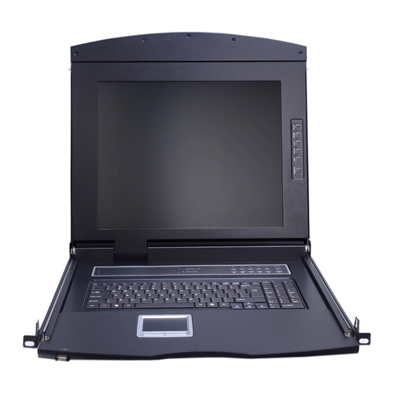
LCD KVM Console User Manual Parts Front View According to the size of the LCD screen is divided into two styles, as shown below, the components of the description please see the figure after the serial number table describes the details. Part Function Description Upper handle... -
Page 18: Rear View
LCD KVM Console User Manual angle of 0-110 degrees LED screen 17 "or 19" LED LCD screen KVM Module KVM modules are free to replace and remove KVM Key panel The KVM Port manual switch function is completed by pressing the key Front mounting The LCD KVM can be installed on the cabinet posts with screws... - Page 19 LCD KVM Console User Manual LCD KVM 8 port CAT5 Rear View LCD KVM 16 port CAT5Rear View LCD KVM 4 port DVI Rear View LCD KVM 8 port DVI Rear View According to the type of KVM ,the rear view of the product can be divided into three categories: ...
-
Page 20: Front View Of The 4: 3 Screen And 16: 9 Screen
LCD KVM Console User Manual Single –rail &Dual-rail LCD Console display Front view of the 4: 3 screen and 16: 9 screen (single-rail): 17inch 4: 3 screen 19inch 16: 9 screen... - Page 21 LCD KVM Console User Manual Front view of the 4: 3 screen(dual-rail): 17inch 4:3 screen 19inch 4:3 screen...
- Page 22 LCD KVM Console User Manual Dual -Rail Slide View Dual-rail overall rear view...
-
Page 23: Overall Dimensions Of The Lcd Kvm
LCD KVM Console User Manual Overall Dimensions of the LCD KVM Single-rail single port KVM Console dimension:... - Page 24 LCD KVM Console User Manual Single –rail multi-ports KVM Console dimension:...
- Page 25 LCD KVM Console User Manual Dual-rail LCD KVM Console dimension:...
-
Page 26: Chapter 2
LCD KVM Console User Manual Chapter 2 Hardware Installation Stacking and Installation Precautions 1. Important safety information regarding the placement of the LCD KVM switch is listed in the appendix, please refer to it before proceeding. 2. Before installation, please make sure that all the devices connected to the power supply are turned off. - Page 27 LCD KVM Console User Manual Slide the switch onto the support flanges. Use the screws supplied with this package to loosely attach the front of the switch to the front of the rack.
-
Page 28: Standard Rack Mounting
LCD KVM Console User Manual Slide the rear attachment sliding brackets along the slide bars until they contact the rear of the switch. Use the screws supplied with this package to attach the bars to the rear of the switch... - Page 29 LCD KVM Console User Manual Built-in mounting bracket installing (All ULS/TLS/DLS Serial products): The built-in mounting bracket comes with a nut, and the fixing nut is welded inside the bending hole at the top of the bracket. Install the bracket into the cabinet mounting post on the upper cabinet, align the bracket mounting holes with the holes in the cabinet mounting column, and then use the screws to fix.
- Page 30 LCD KVM Console User Manual Mounting and fixing in the bracket tail...
- Page 31 LCD KVM Console User Manual Screws mounting position instruction Note: There may be a difference between the two-rail mounting bracket and the single-slide carriage. For the dual-rail product, please refer to the following figure.
-
Page 32: Kvm Modules' Assembly & Removal
LCD KVM Console User Manual KVM Module assembly & disassembly This series of LCD screen and keyboard, mouse and the rear part of the KVM part of the components can be demolished separation, this design allows you to change the KVM components, or KVM components damaged KVM components dismantled after the return to the manufacturer for repair and replace. -
Page 33: Removal Of The Keyboard Module
LCD KVM Console User Manual Disassembly of the Keyboard Module If you need to replace the LCD module part of the keyboard or repair this part, can also be demolished according to the following diagram. 1.The LCD KVM placed in the rack and fixed, the LCD panel turned up, revealing the keyboard, the mouse's operating surface. -
Page 34: Expansion Module Installation
LCD KVM Console User Manual 3. Pull the keyboard from the limit slot gently, find the connection side of the USB interface, remove the USB from connection side, the keyboard could be taken out. Thus completing the demolition of the keyboard module. - Page 35 LCD KVM Console User Manual with the dealer to buy our products supporting the IP module for equipment upgrades and expansion, the operation method is simple and quick, can quickly enhance the integrated management of KVM Application ability. 1. find the rear of the device, expansion slot outside the blank position for installation, you need to prepare a screwdriver for removal and installation tools.
- Page 36 LCD KVM Console User Manual 2.Remove the extended IP module and push it gently into the recess in the mounting module cavity as shown. 3.After pushing the IP module to the bottom, fix the IP module with the two screws that have been removed before.
-
Page 37: Single Device Installation
LCD KVM Console User Manual Single Device Installation Note:Before the installation, make sure that the equipment is powered off. To prevent damage to the equipment during installation, make sure that all the devices installed are well grounded. VGA port KVM module installation To install a single-level KVM, refer to the following online diagrams (numbered in the order of steps on the online graph) and do the following: 1.Plug your USB keyboard and mouse into the USB console port on the back panel of the switch. - Page 38 LCD KVM Console User Manual CAT5 port KVM Module Installation To install a single-level KVM, refer to the following online diagrams (numbered in the order of steps on the online graph) and do the following: 1. Plug your USB keyboard and mouse into the USB console port on the back panel of the switch. 2.Use a set of CAT5e / 6-wire connectors to plug into any available CAT5 Port on the switch.
- Page 39 LCD KVM Console User Manual DVI port KVM module installation To install a single-level KVM, refer to the following online diagrams (numbered in the order of steps on the online graph) and do the following: 1. Plug your USB keyboard and mouse into the USB console port on the back panel of the switch. 2.
-
Page 40: Installation Of Single Port Lcd Kvm Switch
LCD KVM Console User Manual Installation of Single Port LCD KVM Switch... - Page 41 LCD KVM Console User Manual Single-port LCD KVM switch choose KVM cables to connect instead of multi-port use KVM module, divided into two kinds: VGA and DVI according to the port type. VGA Single port LCD KVM...
- Page 42 LCD KVM Console User Manual DVI single port LCD KVM Switch Note:Connect the DP37 port to the corresponding port on the back of the LCD, and then connect the video port of the other end to the video port of the computer. Then connect the port of PS2 or USB to the corresponding keyboard and mouse port of the computer, then power the computer and the LCD KVM switch.
-
Page 43: Cascade Device Connection
LCD KVM Console User Manual Cascade Device Connection This product can be cascaded to increase the number of control devices, combined with IP remote control mode can be flexibly used in a variety of user environment requirements. VGA Port LCD KVM Switch Cascade In the VGA switch Cascade mode, the keyboard, mouse and computer connections is same with the stand-alone connection, this part will not repeat them, the number part of the description is as follows: 1. - Page 44 LCD KVM Console User Manual The connection diagram is shown in the following figure (CAT5PortLCD KVM Switch Cascade).
- Page 45 LCD KVM Console User Manual VGALCD KVM Switch Cascade CAT5LCD KVM Switch Cascade...
-
Page 46: Chapter3
LCD KVM Console User Manual Chapter3 Basic Operation Hot Plug The KVM switch supports hot-plug, removing and removing components by unplugging the cables connected to the computer's port without shutting down the switch. To make the hot swap function work properly, follow these steps: Hot –... -
Page 47: Osd Menu Screen Selection
LCD KVM Console User Manual KVM switch button located in the top of the keyboard operating area, divided into three blocks, from left to right in order is the online indicator display area, Port switch to select the display area, Port switch digital button area. -
Page 48: Hotkey Selection
LCD KVM Console User Manual controlled computer. "No display" means the LCD screen has been powered off. KVM OSD Menu operation (Refer to the OSD Operation chapter for more information.) Hotkey Selection This product offers four hotkey switching methods: 【SCRLL】+【SCRLL】+【NUM】... -
Page 49: Open Way Of Lcd Screen
LCD KVM Console User Manual Open Way of LCD Screen When using, the LCD assembly can be unlocked from the side track by the handle of the upper part of the LCD unit. After unlocking, the LCD module can be pulled out from the slide rail. (Refer to the diagram above for operation) ... - Page 50 LCD KVM Console User Manual AUTO LOCK UNLOCK The screen will automatically pull out the slide after the brake lock device to prevent the random sliding LCD screen components to bring the instability and may cause damage to the user collision. After the brake lock is activated, the LCD screen will limit the operation of pushing the slide rail.
-
Page 51: Chapter4
LCD KVM Console User Manual Chapter4 OSD Operation OSD Introduction OSD (On Screen Display), provides a menu driven interface to handle the computer switching procedure to provide instant access to any computer on the installation. OSD Log in The OSD function provides a two-level (administrator / user) password mechanism. The factory default setting is no need to login password authentication, so you are the first time to open the OSD main menu, no need to enter the login password to enter the OSD main menu screen for the corresponding operation. -
Page 52: Osd Main Menu
LCD KVM Console User Manual OSD Main Menu Active OSD, following picture will be shown on the screen: 【F1】 --- 【F6】 at the bottom of the screen is the function setting of OSD menu, and corresponding operation and setting of corresponding function by keyboard. ... -
Page 53: Osdintroduction Of Function Keys
LCD KVM Console User Manual OSD Function OSD functions are used to configure and control the OSD. For example, you can: rapidly switch to any port; scan selected ports only; limit the list you wish to view; designate a port as a Quick View Port; create or edit a port name;... -
Page 54: F2 Scan
LCD KVM Console User Manual F2 SCAN: The "SCAN" function allows you to perform automatic port scanning of the connected computers. Users can switch ports in order to view the corresponding port computer status. The SCAN function can automatically scan from current selected port, the scan interval can be set by users. -
Page 55: F4 Qv
LCD KVM Console User Manual F4 QV: QV function can select port as Quick View. Move the highlight bar to a port, press [F4], an icon of up triangle appears. Press [F4] again, the icon disappears. F5 EDIT: EDIT function creates or edits the name of a port. Press [F5], a pink edit box will appear on the screen. Input name, and then press [Enter], the port is set a name and it will also appear on the screen. - Page 56 LCD KVM Console User Manual To change your settings: 1. Move the selection column to this option, press 【Enter】to enter a setting option. 2.After selecting an item, the sub-menu and the further options provided will appear. To select it, double-click the mouse or move the selection column to the option, and then press the [Enter] key, an icon will appear.
-
Page 57: Osd Activating Hotkey
LCD KVM Console User Manual OSD ACTIVATING HOTKEY It provides you with four hotkey combinations: You can use the keyboard 【↑】 【↓】 to move cursor to select, and then press 【Enter】 key to save. The default is to use 【CTRL】【CTRL】as the OSD menu start hotkey. SWITCH HOTKEY It provides you with four hotkey combinations: 【SCRLL】【SCRLL】【NUM】、【CTRL】【CTRL】【NUM】、【ALT】【ALT】【NUM】、... -
Page 58: Scan Duration
LCD KVM Console User Manual SCAN DURATION Duration for scanning one port. Options are 3 seconds, 5 seconds, 10 seconds, 15 seconds, 20 seconds, 30 seconds, 40 seconds, 60 seconds. Move the highlight bar to an option and press [Enter] to select it. SET PASSWORD Set new password. -
Page 59: Clear The Name List
LCD KVM Console User Manual CLEAR THE NAME LIST This function clears the name of a port in the OSD menu. If you use this function, all the port names will be emptied, so please do it carefully. When doing this, you need to verify the password of the administrator, input 【Y】key, then press【Enter】... -
Page 60: Appendix
LCD KVM Console User Manual Appendix Safety Instruction In General This product is for indoor use only. Please read all the instructions for future reference. Follow all the warnings and instructions on the device. Do not place this equipment on any unstable surface (such as cart, stand, table, etc.). If this equipment falls, it will cause serious damage. -
Page 61: Rack Mounting
LCD KVM Console User Manual The function of the device is obviously changed The machine can’t be operated normally as instructed by the operating instructions. Adjustment only for the control functions covered by the operating instructions, and other inappropriate operations may cause damage, requiring more qualified personnel to perform repairs Cabinet Installation ... -
Page 62: Product Specifications
LCD KVM Console User Manual Specification VGA Series LCD KVM Switch Specification Type 1 Port 4 Port 8 Port 16 Port Model AS-7100ULS AS-7104ULS AS-7108ULS AS-7116ULS Direct Connects Computer Connection Maximum Connects OSD Menu, Front panel buttons, Hot Key, IP CPU Port Selection Remote Control (Optional) Console Connector... - Page 63 LCD KVM Console User Manual CAT5 Series LCD KVM Switch Specification Type 4 Port 8 Port 16 Port Model AS-7104TLS AS-7108TLS AS-7116TLS Direct Connects Computer Connection Maximum Connects OSD Menu, Front panel buttons, Hot Key, IP CPU Port Selection Remote Control (Optional) Console Connector DB 37PIN 16 x VGA...
- Page 64 LCD KVM Console User Manual DVI Series LCD KVM Switch Specification Type 1 Port 4 Port 8 Port Model AS-7100DLS AS-7104DLS AS-7108DLS Computer Direct Connects Connection CPU Port Selection OSD Menu, Front panel buttons, Hot Key Console Connector DB 37PIN Expansion 1 x USB Type A Female (Front expansion Interface...
-
Page 65: Lcd Module Specifications
LCD KVM Console User Manual LCD Module Specifications Function 17 inch LCD module 19 inch LCD module 19 inch wide-screen LCD module LCD Screen Size 17inch4:3 19inch4:3 19inch16:9 Display Ratio Assembly LCD Screen SXGA TFT-LCD Wide AHVA TFT-LCD Type Viewing Area 337.920(H) ×... -
Page 66: Warranty Conditions
LCD KVM Console User Manual Warranty Conditions The Company shall not be liable for damages up to the amount paid by the Customer for the Products. In addition, the Company does not assume any direct, indirect, special, incidental or consequential damages resulting from the use of this product or the enclosed CD-ROM, documentation, etc…;...
Need help?
Do you have a question about the AS-7100 Series and is the answer not in the manual?
Questions and answers