Table of Contents
Advertisement
Quick Links
Advertisement
Table of Contents

Related Manuals for Telecard R-002PP

Summary of Contents for Telecard R-002PP
- Page 1 VHF RADIO R-002PP Operation manual ААНЗ.464424.027.61 РЭ...
-
Page 2: Table Of Contents
ААН3.464424.027.61 РЭ p.2 Contents 1 Description and Performance 1.1 Purpose 1.2 Technical Specifications 1.3 Configuration 1.4 Component Parts Description 1.4.1 Transceiver 1.4.2 Headset 1.4.3 Antenna 1.4.4 Battery Pack 1.4.5 Battery Chargers С-1001 (С-1002) 1.4.6 Fillgun 1.4.7 Assembly Parts Set 1.5 Radio Control 1.6 Meters, Tools and Accessories 1.7 Marking and Sealing 1.8 Packaging... - Page 3 ААН3.464424.027.61 РЭ p.3 2.3.4 Volume Adjust 2.3.5 Touch-Tone Call 2.3.6 Power Level Setup 2.3.7 Operation with the Squelch 2.3.8 Selection of the DTE...
-
Page 4: Description And Performance
ААН3.464424.027.61 РЭ p.4 1 Description and Performance 1.1 Purpose The radio, carried by the personnel, is designed to provide tactical communications both in stationary and battlefield conditions. The radio provides the possibility to transmit and receive voice and data (digital information) while operating on the fixed frequencies (non-ECCM mode) and in the ECCM mode. -
Page 5: Technical Specifications
ААН3.464424.027.61 РЭ p.5 Stand-by power saving receive is advisable to be used to extend operating time of the radio from one battery pack without recharging. While operating on fixed frequencies, voice information is transmitted in: F3 analog form, which provides connection of the radio through the link with the radios of other types, older radio systems in particular;... - Page 6 ААН3.464424.027.61 РЭ p.6 1.2.2 Transmitter Specifications: The power output is the following: Nominal power output – (2 ± 0,4)W; Low power output – ( 0,5± 0,08)W; Attention! When the radio is in use, it should be noted that the more output power is, the longer the operating distance is.
-
Page 7: Configuration
ААН3.464424.027.61 РЭ p.7 Power supply is ensured by the Battery Pack. The radio provides settings if nominal voltage of the battery pack is (7,2-7,4)V. Performance control of the battery is done by the embedded control system. The results are shown on the radio display (front panel of the Transceiver Unit). - Page 8 ААН3.464424.027.61 РЭ p.8 Example of record of radio notation during the order: “2W ТУ У32.2-13881657-016:2007 R-002-PP PORTABLE RADIO (ААНЗ.464424.027 ТУ)”-option-02, where: - 2W R-002-PP VHF PORTABLE RADIO ТУ У32.2-13881657-016:2007 - notation and code; - ААНЗ.464424.027 ТУ – notation of technical conditions; - option-02 –...
- Page 9 ААН3.464424.027.61 РЭ p.9 Figure 1 – Radio Assembly Drawing...
- Page 10 ААН3.464424.027.61 РЭ p.10 а ) Battery Charger С-1001...
- Page 11 ААН3.464424.027.61 РЭ p.11 б) Battery Charger С-1002 Figure 2 – С-1001, С-1002 Battery Charger Assembly Drawing Data communication is provided by the PC or special equipment. The PC or special equipment is connected to the radio via the “DATA” connector, which is on the left side of the radio.
- Page 12 ААН3.464424.027.61 РЭ p.12 While placing the radio components into the bag, it should be taken into consideration that: Transceiver, connected to the Battery Pack, should be first placed into the ЧП- 01-Р-002ПП Cover for the transceiver (hereinafter referred to as Cover for the transceiver) and then put into the bag;...
- Page 13 ААН3.464424.027.61 РЭ p.13 Comp. №4 Headset Antenna Shorted Antenna Transceiver Comp. №3 Comp. №2 Comp. №1 Battery pack Battery Pack Fillgun Figure 4 - Carrying bag radio Figure 5 - Cover for the transceiver, overall view...
-
Page 14: Component Parts Description
ААН3.464424.027.61 РЭ p.14 Figure 6 - Cover for battery pack, overall view While operating the radio it should be noted that: fillgun is used only to program the radio, in addition, one device may be used to program a set of radios. Constant connection of fillgun to the Transceiver is useless. The connections, other than defined in the assembly drawing, are not allowed. - Page 15 ААН3.464424.027.61 РЭ p.15 display, marked with 7; silicone keypad, marked with 8. RF- connector of the BNC-type, marked with 9, for antenna connection, connector, marked with 10, for headset connection, rotary power switch, marked with 11 are on the top panel of the housing.
- Page 16 ААН3.464424.027.61 РЭ p.16 Figure 7 – Transceiver, overall view...
- Page 17 ААН3.464424.027.61 РЭ p.17 Figure 8 - Battery Pack Assembling, overall view The keypad is intended for radio control. It is used to provide the following functions: a) selection of preprogrammed channel; b) resonant frequency setup or change; c) adjustment of the output power level; d) mode of operation setup or change, i.e., voice or data communications;...
-
Page 18: Headset
ААН3.464424.027.61 РЭ p.18 Figure 9 – Keypad of the radio, overall view 1- MENU 4- FREQ (FREQUENCY) 7- PWR (POWER) 8- MODE 9- MSG (MESSAGE) . CLR (CLEAR) 0- SET ENT (ENT) 1.4.2 Headset The headset is intended for the radio operator to ease the radio communication and to provide voice communications. - Page 19 ААН3.464424.027.61 РЭ p.19 The headset view is presented in Fig. 10. The view of the headset placed on the operator’s head and “PUSH-TO-TAL ” button placed on operator’s hand is presented in Figures 11, 12. Headphone Bandage Headset cable PUSH-TO- TALK button Connector Microphone...
-
Page 20: Antenna
ААН3.464424.027.61 РЭ p.20 1.4.3 Antenna Antenna is designed to process the energy of the electric signals into the energy of electromagnetic field and vice versa. antennas included into delivery set: ANT-R002PP ААНЗ.468577.013.61 Antenna (hereinafter – antenna) ANT-R002PP-01 ААНЗ.468577.014.61 Shorted Antenna (hereinafter – Shorted Antenna). Antenna is intended to obtain maximum communication range (3-5 km), and Shorted Antenna is intended to increase communication range up to the hundreds of meters. -
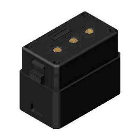
Page 21: Battery Pack
ААН3.464424.027.61 РЭ p.21 Figure14 – Antenna, overall view during the performance 1.4.4 Battery Pack Battery pack supplies power to the radio during its operation. Overall view of the Battery Pack is shown in Figure 15. Battery pack consists of two tandem lithium-ions batteries. The output voltage is (7,2- 7,4) V. - Page 22 ААН3.464424.027.61 РЭ p.22 («Minus») («Plus») Figure15 – Battery Pack, overall view...
-
Page 23: Battery Chargers С-1001 (С-1002)
ААН3.464424.027.61 РЭ p.23 1.4.5 С-1001 (С-1002) Battery Charger С-1001 (С-1002) Battery Charger are designed to charge one or two battery packs, respectively. Battery Charger is operated in the following environmental conditions: temperature of ambient air is in the range from 263 to 323K (from -10° to +50°... - Page 24 ААН3.464424.027.61 РЭ p.24 1 – power LED; 2 – battery pack connection jack; 3 – charge indicator; 4 – 12/27V connector, covered up with terminator; 5 – 2 A fuse; 6 – ON/OFF switch. Figure16 – С – 1001 Battery Charger, overall view 1...
- Page 25 ААН3.464424.027.61 РЭ p.25 1 – battery pack connection jacks; 2 – charge indicator; 3 – power LED; 4 – 12/27V connector, covered up with terminator; 5 – 4 A fuse; 6 – ON/OFF switch. Figure17– С – 1002 Battery Charger, overall view...
-
Page 26: Fillgun
ААН3.464424.027.61 РЭ p.26 1.4.6 Fillgun Fillgun (hereinafter referred to as the Unit) is intended to record data from the PC for radio programming, storage of recorded data, and dubbing the information into the radio. The unit ensures data communications between the PC (data recording to the device) and the radio (dubbing the information) on RS-232 interface. -
Page 27: Assembly Parts Set
ААН3.464424.027.61 РЭ p.27 Power supply of the device is provided by the batteries, installed in the device. When the power switch is in ON position, indicator lights are blinking, which means that the batteries are operative. Constant light of indicators means that the batteries are out of order. 1.4.7 Assembly Parts Set Assembly Parts Set is designed to assembly the radio on the objects of installation and to program the radio. -
Page 28: Meters, Tools And Accessories
ААН3.464424.027.61 РЭ p.28 adjustment of radio output power level volume control This will be enough to operate the radio by the unskilled personnel. 1.5.2 Radio’s software provides channel programming before and during radio performance. While programming the radio the following parameters are added to radiodata: operating frequency;... -
Page 29: Packaging
ААН3.464424.027.61 РЭ p.29 1.7.4. Shipping container is marked with main, additional, informative letterings and handling symbols. 1.7.5. Sealing of the radio is made in the screw holes that are on the rear and front lids of the Transceiver, filled with heat resistant mastic. Sealing of the Battery Charger is done, using heat resistant mastic for sealing. - Page 30 ААН3.464424.027.61 РЭ p.30 Battery pack, together with the label and a packet with silica gel, is to be put into plastic bag. Solder the bag and pack it up above the cover with reserved battery pack in the compartment №3 of the Carrying bag radio. Transceiver is to be wrapped, tied up with pack thread.
- Page 31 ААН3.464424.027.61 РЭ p.31 Headset is to be wrapped, tied up with pack thread, and put the label beneath the thread. Headset, wrapped with paper, and a packet with silica gel is to be put into the plastic bag, which should be soldered thereafter, and packed into compartment №1 of the Carrying bag radio.
- Page 32 ААН3.464424.027.61 РЭ p.32 Maintenance documentation, CD-R disk Packing List Figure 20 – Scheme of radio packaging into the shipping container...
- Page 33 ААН3.464424.027.61 РЭ p.33 Figure 21 – Scheme of radio packaging (with the Battery Charger), into the shipping container...
-
Page 34: Proper Use
ААН3.464424.027.61 РЭ p.34 2 Proper use 2.1. Operating limits Radio should be operated by personnel who know radio construct and its performance. To avoid premature deterioration of the radio and its damage during the service keep to the following precautions: Do not expose component parts of the radio to dust and other contamination;... -
Page 35: Getting Started
ААН3.464424.027.61 РЭ p.35 Do not connect antenna or adjust its position when the radio operates in transmission mode. Do not install the Battery Pack into the Battery Charger when it is turned off to avoid full discharge of the Battery Pack or its shut down. It is not recommended to keep the Battery Pack in the Battery Charger for the long time after the charging has been finished. -
Page 36: Turning The Radio On
ААН3.464424.027.61 РЭ p.36 when charging is finished, remove the battery pack from the Battery Charger and switch the Battery Charger off. Connect the battery pack to the Transceiver Put the Transceiver with connected Battery Pack into the cover. Connect the Headset to the Transceiver, if necessary. Connect antenna to the transcei er’s antenna input. -
Page 37: Turning The Radio Off
ААН3.464424.027.61 РЭ p.37 2.2.4. Turning the Radio Off Adjust “ON-OFF” switch in the «OFF» position to turn the radio off. When the radio is turned off, the last value of setting is saved, i.e., data of the operating channel are saved in the radio’s memory. - Page 38 ААН3.464424.027.61 РЭ p.38 3 9. 5 0 0. 0 2. 0 W 6 0. 0 0 0. 0 █ F 3 E █ А R █ Figure 25. Example of indication appeared on the display after the radio initialization. 3 0. 0 0 0. 0 2.
- Page 39 ААН3.464424.027.61 РЭ p.39 █ symbol in the sixteenth column indicates the audio frequency amplifier gain while receiving voice messages. The higher is the column, the higher is the audio frequency amplifier gain as well as the radio output volume during the reception. Digits in the (2, 6-7) positions indicate the setup level of the radio output power measured in watts and marked in the table with letter W.
- Page 40 ААН3.464424.027.61 РЭ p.40 3 0. 0 0 0. 0 2. 0 W 1 0 9. 9 7 5. 0 а А 3 3 1 █ 1. 2 █ Figure 27. Example message shown on the indicator during data communications with the rate of 1,2 Kbps During voice communications symbols TLF, and IH, respectively, are shown in (3, 7), (3, 8), (3, 9) positions.
-
Page 41: Supplementary Data On Fixed Frequencies Indication
ААН3.464424.027.61 РЭ p.41 In reception mode the output signal level of the Transceiver is controlled. If the output power le el is not adequate to the preset output power, then the “*” symbol appears in the (4,13) position. indication in the (4,14) shows the battery state indication (5 dashes – full charge battery). -
Page 42: Supplementary Data On Fhss Mode Indication
ААН3.464424.027.61 РЭ p.42 - (1, 15), (2, 15) - hundreds of hertz. While operating in the F3 mode with squelch, the «^» symbol is displayed in the (4, 8) position and the symbol is displayed in the (4, 6) position: the «^»... - Page 43 ААН3.464424.027.61 РЭ p.43 Press the “4” (FREQ) key. The display shows indications, as illustrated in Figure 28. * * * * * * * 0. 5 W Т L F █ F 3 E █ А R █ Figure 28. The example indication showed on display after the “FREQ”- key has been pressed Enter the operating frequency, using keys from “0”...
-
Page 44: Mode (Emission Class) Setting From The Front Panel
ААН3.464424.027.61 РЭ p.44 To enter the frequency with the value of 34,5125 MHz, press the keys in the following order: “3”, “4”, “.”, “5”, “1”, “2”, “.”, “5”, “ENT”. Examples of frequency entering for double-frequency simplex mode: The procedure of receive (transmit) frequency entering in double-frequency simplex mode is similar to described above for simplex mode. -
Page 45: Preset Channel Selection
ААН3.464424.027.61 РЭ p.45 TLF indicates operation with the headset; receiver output power level is adjustable; TLF□ indicates operation with the headset; receiver output power level is not adjustable. IH indicates operation directly from the transceiver; receiver output power level is adjustable. - Page 46 ААН3.464424.027.61 РЭ p.46 2.3.4 Volume Adjust Use the volume control knobs (marked with 13 in Figure 7) on the left flank of transceiver housing to adjust the volume of the radio. Knobs are marked with «↓» and «↑» symbols. «↓» key is used to decrease the volume, and «↑» key is used to increase the volume.
- Page 47 ААН3.464424.027.61 РЭ p.47 2.3.7. Operation with the Squelch Squelch is used only while voice is transmitting on fixed frequencies in the F3E class. Squelch is designed to turn off the audio frequency amplifier of the radio’s recei er when there is no desired signal on the receiver input, or when the noise voltage- to-desired signal oltage ratio is poor.
Need help?
Do you have a question about the R-002PP and is the answer not in the manual?
Questions and answers