Table of Contents
Advertisement
Quick Links
Advertisement
Table of Contents

Summary of Contents for Mebay HM500
- Page 1 HM500 DISPLAY PANEL OF GENERATOR CONTROLLER USER MANUAL V1.1...
- Page 2 HM500 DISPLAY PANEL OF GENERATOR CONTROLLER USER MANUAL Version Version Date Note V1.0 2020-07-1 Original release. V1.1 2020-12-22 Update AUX option description Chongqing Mebay Technology Co.,Ltd Add: No6-2,Building 4, Gangan Rd, Jiangbei District, Chongqing. Tel:+86-23-6869 3061 Fax:+86-23-6765 8207 Web:http://www.mebay.cn http://www.cqmb.cn...
- Page 3 HM500 DISPLAY PANEL OF GENERATOR CONTROLLER USER MANUAL Symbol Description Symbol Description Remind operators to operate correctly, otherwise it may cause the equipment not to work correctly. Note It is indicated that potential hazards can damage equipment without proper precautions.
- Page 4 HM500 DISPLAY PANEL OF GENERATOR CONTROLLER USER MANUAL Warning 1. The installation of this equipment must be carried out by professionals. 2. When installing and operating the controller, please read the entire instruction manual first. 3. Any maintenance and commissioning of the equipment must be familiar with all the equipment.
-
Page 5: Table Of Contents
1. All rights reserved. No part of this duplication may be reproduced in any material form (including photocopying or storing in any medium by electronic means or others) without the written permission of the copyright holder. 2. MEBAY Technology reserves the rights to change the contents of this document without prior notice. -
Page 6: Summary
HM500 DISPLAY PANEL OF GENERATOR CONTROLLER USER MANUAL 1. Summary This display panel controller is specially designed for the display of FM700 series products, and has the functions of starting, stopping, parameter monitoring, fault monitoring and parameter setting. 3.5inch LCD screen display with brand new UI design is adapted in this controller that the relative failures can be displayed directly. -
Page 7: Overall Dimension And Wiring Diagram
HM500 DISPLAY PANEL OF GENERATOR CONTROLLER USER MANUAL 4. Overall Dimension and Wiring Diagram Overall Dimension:... -
Page 8: Installation Instruction
HM500 DISPLAY PANEL OF GENERATOR CONTROLLER USER MANUAL HM500 Descriptions of terminal connection Function Description 5-position terminal Connect to the main control board. 5. Installation instruction The controller is fixed by four special fixing members and screws, and the screws of the metal fasteners cannot be too tight. -
Page 9: Control And Operation Instruction
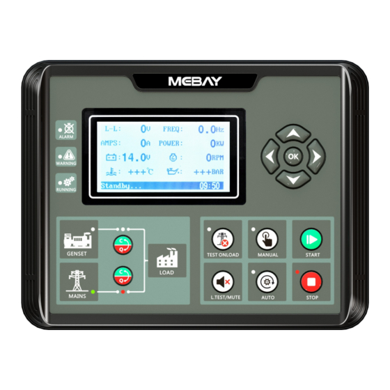
HM500 DISPLAY PANEL OF GENERATOR CONTROLLER USER MANUAL 6. Panel and display Left OK/HOME Right Alarm Down Warning Running anual Gens on load Manual Start Gens status Stop Mains Status Auto Mains on load Close/On Test LED Test/MUTE 7. Control and operation instruction ... - Page 10 Records checking any buttons pressed to exit from the page. Alarm records checking HM500 controller can save 14 group of alarm records which contains the alarm record data includes detailed data such as alarm time, generator parameters, engine parameters, etc.
-
Page 11: Control And Operation Instruction
HM500 DISPLAY PANEL OF GENERATOR CONTROLLER USER MANUAL 3) Press to turn lower records under records checking page. Press turn upper records and press to revert back to alarm history records page. 4) Exit from records page: In the history records page and checking page, press to exit. - Page 12 HM500 DISPLAY PANEL OF GENERATOR CONTROLLER USER MANUAL Longest Longest Longest voltage rated speed temperature built/ warming increasing increasing runn- Cooling increasing up time time time running time time Stop Start Rated speed Rated speed idle Safe idle time time...
-
Page 13: Warnings And Shutdown Alarms
HM500 DISPLAY PANEL OF GENERATOR CONTROLLER USER MANUAL Notices in Starting Process Note 1: During the Cranking time, the controller automatically detects the speed signal, frequency signal and oil pressure value or the charging voltage (according to the parameter setting) to reach the judgment condition of successful start, then the judgment is that the start is successful and the motor relay is closed. - Page 14 HM500 DISPLAY PANEL OF GENERATOR CONTROLLER USER MANUAL Notes: Warning is a non-serious failure state, which will not harm the gensets system for the time being. It only reminds operators to pay attention to the situation that does not meet the requirements and solve it in time to ensure the continuous operation of the system.
- Page 15 HM500 DISPLAY PANEL OF GENERATOR CONTROLLER USER MANUAL When the controller detects that the programmable input "Low fuel level warning input" switch is active, it starts warning delay and lasts for Normal alarm delay. When the "Low fuel level warning input" switch is enabled, the engine low fuel level switch warning is reported.
- Page 16 HM500 DISPLAY PANEL OF GENERATOR CONTROLLER USER MANUAL screen. ECU faults warning When the controller detects the warning information of ECU, Then start warning delay and the duration (Normal alarm delay) have not returned to normal, the warning of ECU faults warning is reported. "WARNING" lights will light up, Generators will not stop, displays "ECU faults warn"...
- Page 17 HM500 DISPLAY PANEL OF GENERATOR CONTROLLER USER MANUAL Shutdown Alarms Communication failure When the controller detects that the display panel communication with FM7000 is disconnected, the alarm delay starts and the communication failure with the display panel continues for 20S, and then reports the failure of the main control board communication failure, and the general alarm light "ALARM"...
- Page 18 HM500 DISPLAY PANEL OF GENERATOR CONTROLLER USER MANUAL When the controller detects that the programmable input port "High temperature alarm switch" switch is active. Start low oil pressure switch alarm delay, for a period of time "Normal alarm delay" programmable input port "High temperature alarm switch"...
- Page 19 HM500 DISPLAY PANEL OF GENERATOR CONTROLLER USER MANUAL Temperature sensor open" on the current fault screen. Fuel Level sensor disconnected alarm When the controller parameter "Action if fuel Level sensor disconnected " is set to "alarm", When the fuel Level sensor is detected to be disconnected, Then start alarm delay and the duration (Normal alarm delay) have not returned to normal, the alarm of fuel Level sensor disconnected alarm is reported.
- Page 20 HM500 DISPLAY PANEL OF GENERATOR CONTROLLER USER MANUAL duration (Normal alarm delay) have not returned to normal, the alarm of Non-balance current ratio is reported. "ALARM" lights will light up, Generator stops running, displays " Unbalance of AMP " on the current fault screen.
-
Page 21: Parameters Setting
HM500 DISPLAY PANEL OF GENERATOR CONTROLLER USER MANUAL "Louver status input" switch is enabled, the Louver status input alarm is reported. "ALARM" lights will light up, Generator stops running, displays "Louver abnormal" on the current fault screen. Emergency stop alarm... - Page 22 HM500 DISPLAY PANEL OF GENERATOR CONTROLLER USER MANUAL display error if password is wrong. The correct password should be put after pressing any button. 5) Press to turn the digit into upper position, press to turn the digit into lower position, press to get into parameters setting page.
- Page 23 HM500 DISPLAY PANEL OF GENERATOR CONTROLLER USER MANUAL Setting generator rated frequency to 40.0-80.0Hz Rated frequency choose the meter range and calculate the (50.0Hz) alarm value. Setting generator phase voltage to choose Rated phase 80-360V(230V) the meter range and calculate the alarm voltage value.
- Page 24 HM500 DISPLAY PANEL OF GENERATOR CONTROLLER USER MANUAL sensor 1: User-defined types, it can be User-defined. 2: 0-100Ω 3: 100-0Ω 4: 0-107Ω 5: 107-0Ω 6: 0-180Ω 7: 180-0Ω 8: 180-10Ω 9: 10-180Ω 10: 120-10Ω 11:10-120Ω 12: 90-0Ω 13: 0-90Ω 14: 0-30Ω...
- Page 25 HM500 DISPLAY PANEL OF GENERATOR CONTROLLER USER MANUAL Action if fuel Disable Level Warning Action if Fuel level sensor disconnected. sensor Alarm and stop disconnected ℃/KPA ℃/BAR Pressure/Tempe ℃/PSI Unit display. rature unit ℉/KPA ℉/BAR ℉/PSI 2)Basic Setting 2 No Parameter...
- Page 26 HM500 DISPLAY PANEL OF GENERATOR CONTROLLER USER MANUAL it as crank success, motor escaped. Rated RPM multiplying by this value is regarded as crank success condition. 8 RPM disconnect 0-200% (24%) When the RPM is over the condition value, then system regards it as crank success, motor escaped.
- Page 27 HM500 DISPLAY PANEL OF GENERATOR CONTROLLER USER MANUAL supply than setting value, then pre-oil supply stopped. 4 Cranking time 3.0-60.0s (8.0s) The time when the starter is on power. 3.0-60.0s If crank failure, the waiting time before the second 5 Crank rest time (10.0s)
- Page 28 HM500 DISPLAY PANEL OF GENERATOR CONTROLLER USER MANUAL phase current delay] is set to 0. The over current 【inverse time】 delay is inverse time, and the formula is T=t/((IA/IT) -1)^2. This option will not take effect until the [24-Over Over power total power delay] is set to 0.
- Page 29 HM500 DISPLAY PANEL OF GENERATOR CONTROLLER USER MANUAL faults delay), then low fuel level alarms. if the value is set as 0, then the under speed alarm is disabled. Rated battery voltage multiplying by this value is regarded as over battery voltage warning value. When...
- Page 30 HM500 DISPLAY PANEL OF GENERATOR CONTROLLER USER MANUAL higher than the value and comes into over current delay but still higher (over current faults delay), then over current alarms, If the value is set as 200, then the alarm is disabled.
- Page 31 HM500 DISPLAY PANEL OF GENERATOR CONTROLLER USER MANUAL if there is no frequency under high speed status. 14. Gens load: continuous or pulse type according to time setting. 15. Gens unload: continuous or pulse type according to time setting. 16. Speed-down control: the output time is shutdown idle delay during shutdown idle or shutdown on power procession.
- Page 32 HM500 DISPLAY PANEL OF GENERATOR CONTROLLER USER MANUAL 13. Mains un/loading input: connect to auxiliary point of mains loading switch. 14. Shades status input. 15. Auto start disabled: gens will not start if there is signal input whatever mains normal or not.
- Page 33 HM500 DISPLAY PANEL OF GENERATOR CONTROLLER USER MANUAL The working plan will be executed according the chosen date when setting as every month. The working plan will be executed according the chosen date when setting as every week. From 1...
-
Page 34: Fault Finding
HM500 DISPLAY PANEL OF GENERATOR CONTROLLER USER MANUAL under standby button pressed after delay. If setting as (6000.0s) 6000.0s: disabled. a) USB/485 PORT No Parameter Range(default) Notes 1 Controller ID 1-255(16) The IP built by controller and PC. 0-4800 1-9600... - Page 35 HM500 DISPLAY PANEL OF GENERATOR CONTROLLER USER MANUAL Check the emergency stop button. Genset Emergency Check that the voltage of the controller's 3 feet to the ground Stop should be the battery voltage. Check the controller connection. Check oil pressure sensor and its wiring.
Need help?
Do you have a question about the HM500 and is the answer not in the manual?
Questions and answers