Table of Contents
Advertisement
Quick Links
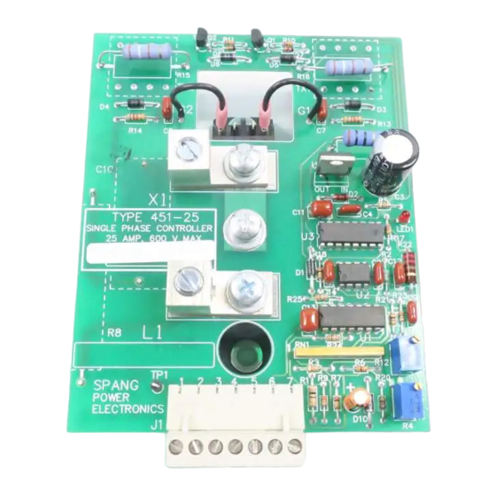
OUTLINE:
The outline and mounting dimensions of the
are shown in Figure 1, below.
C5
D4
R14
C8
C10
TYPE 451-25
SINGLE PHASE CONTROLLER
25 AMP, 600 V MAX.
SN
R8
SPANG
POWER CONTROL
J1
FIGURE 1: OUTLINE AND MOUNTING
MOUNTING:
The type 451-25 controller is supplied as a modular assembly, and is
intended to be mounted in a customer supplied enclosure. The mounting
holes are 1/4" in diameter, and the use of a 10-32 UNF machine screw,
with a flat washer and a lock washer is recommended.
applications, the heat transfer through the base of the module into a steel
or aluminum
compound applied) will provide adequate cooling. A mounting torque
of about 44 lb. in. ± 15% is recommended.
SAFETY:
When possible, the control common (connector J1 pins 2 and 7) should
be tied to earth ground. This should be a single point ground in order to
avoid the possibility of noise being generated by circulating ground
currents.
DANGEROUSLY HIGH VOLTAGES ARE PRESENT WHEN POWER
IS APPLIED TO THE UNIT, WHETHER THE CONTROLLER IS
OPERATING OR NOT.
POWER
IS
REMOVED
DISCONNECTING
WIRES,
CONTACT WITH INTERNAL CIRCUITRY.
INSTALLATION
451-25 AC Controller
TYPE
4.000
Q2
C6
R10
Q1
R11
D6
D5
R15
R16
TX2
TX1
D3
G2
G1
R13
C7
G2
G1
R19
GND
U4
OUT
IN
D2
C3
R5
C5
C4
LED1
R17
U3
R22
R18
C2
R2
D1
U2
R21
C9
U1
BIAS
RN1
1
R3
R6
R12
R9 R7
R20
R1
1
2
3 4
5
6
7
C1
TP1
R4
GAIN
For most
panel (with paint removed and a thermal
CAUTION
ALLOW AT LEAST 1 MINUTE AFTER
BEFORE
CONNECTING
OR
OTHERWISE
COMING
2
WIRING CONNECTIONS - POWER
WIRING CONNECTIONS - CONTROL POWER
WIRING CONNECTIONS - CONTROL
OR
IN
The controller power input is connected to terminal L1. The load is connected from
terminal X1 to the return side of the power source. See Figure 2 for a typical
connection diagram. A power source rated between 120 - 575 V, 1∅, 50/60 Hz
capable of supplying the required load current (up to 25 A
size should be determined by the applicable wiring codes for the specific
installation. The terminals will accept wire gauges of 2 - 14 AWG, with a strip
length of 3/8" recommended. It is expected that 12 AWG wire will typically be
used, with an appropriate breaker or fuse provided.
The control power input is connected to J1, terminals 6 and 7. A 24 VAC isolated
power source, which is in phase with the main power source must be used. See
Figure 2 for a typical connection diagram.
L1
ISOLATION
TRANSFORMER
J1
PIN 6
120 - 575 V
24 VAC
POWER SOURCE
J1
PIN 7
FIGURE 2: TYPICAL CONNECTION DIAGRAM
Figure 3 shows a typical method of connecting the control signals to the 451-25. In
this typical setup, a Remote / Local switch or relay is used to select which input
signal is used. In the Local position, a 10K potentiometer is used to generate a 0 - 5
VDC control signal, and the voltage output from the 4 - 20 mA source (J1 pin 5) is
disconnected. In the remote position, a 4 - 20 mA source is used to generate the
control signal, which is connected to J1 pin 3, and the 10K potentiometer is
disconnected.
On / off control may be realized by connecting a switch between J1 pin 4 and J1
pin 7. The unit will be held off when this switch is closed.
If the controls are located at some distance from the unit (i.e. if they are not in the
door of the enclosure) shielded cable should be used. Wire size is not important,
other than it should be between 12 and 28 AWG to fit the connectors.
3
) is required. Wire
RMS
X1
451-25
POWER CONTROLLER
LOAD
Advertisement
Table of Contents

Related Manuals for Spang Power Electronics 451-25

Summary of Contents for Spang Power Electronics 451-25
- Page 1 When possible, the control common (connector J1 pins 2 and 7) should Figure 3 shows a typical method of connecting the control signals to the 451-25. In be tied to earth ground. This should be a single point ground in order to...
- Page 2 WEIGHT Pressure type, accepts #2 - #14 AWG CONNECTIONS The information contained in this manual is the property of Spang Power Electronics. wire. Strip length = 3/8″ - 1/2”. POWER Transmittal, receipt or possession of this information does not comply, license or imply any...
Need help?
Do you have a question about the 451-25 and is the answer not in the manual?
Questions and answers