
Summary of Contents for infiniDome OtoSphere V2 - EPS
- Page 1 2020 OtoSphere V2 - EPS Installation Manual INFINIDOME – THE WIRELESS SECURITY COMPANY...
-
Page 2: Table Of Contents
Troubleshooting ..........................10 Problem: Nothing is working, and my GPS receiver does not acquire lock ........10 Interference Indication ......................... 10 Interference Indication Integration Instructions ................10 infiniDome Ltd. Web: www.infinidome.com c/o Focus Telecom Ltd. Mail: info@infinidome.com 7 Haeshel St., Industrial Park (South) Tel: +972-4-770-7700 P.O.Box 3558, Caesarea 3088900, ISRAEL... -
Page 3: Introduction
Two active GPS antennas, with nominal gain of 26dB, are connected to the SMA RF connectors; the primary and auxiliary antenna inputs. The RF Output provides connection to the input of the GPS Receiver. infiniDome Ltd. Web: www.infinidome.com c/o Focus Telecom Ltd. -
Page 4: Interfaces
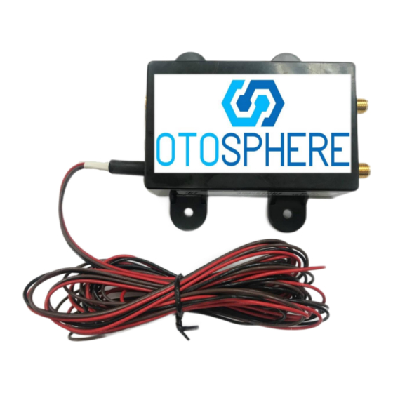
Black: GND Brown: Open drain interference indication. (This wire sends an indication when the unit is detecting and protecting against a hostile signal). Figure 1 - OtoSphere v2 - EPS - General Overview infiniDome Ltd. Web: www.infinidome.com c/o Focus Telecom Ltd. -
Page 5: Cautions
WEEE registration number WEE/GK2929WW RF Interfaces Antenna Connectors (P/A) 50Ω SMA 2.75VDC designed for 26dB ±2dB gain Receiver Connector (R) 50Ω SMA infiniDome Ltd. Web: www.infinidome.com c/o Focus Telecom Ltd. Mail: info@infinidome.com 7 Haeshel St., Industrial Park (South) Tel: +972-4-770-7700 P.O.Box 3558, Caesarea 3088900, ISRAEL... -
Page 6: Installation
Two antennas are connected to the module (supplied antennas or locally purchased for permanent installation); the GPS antenna connects to primary input ‘P’ and an additional antenna connects to the auxiliary input ‘A.’ Figure 2 - GPS Receiver with OtoSphere v2 - EPS Integrated infiniDome Ltd. Web: www.infinidome.com c/o Focus Telecom Ltd. -
Page 7: Sma Cables Connectors
Ensure that there is a distance of at least 15cm between the two antennas (nominally > 25 cm). Route the antenna cables away from moving parts, under carpet and behind plastic trim, to the OtoSphere unit location. infiniDome Ltd. Web: www.infinidome.com c/o Focus Telecom Ltd. Mail: info@infinidome.com 7 Haeshel St., Industrial Park (South) - Page 8 If possible, increase the distance between the OtoSphere antennas and any jamming source. For example, if there is a jammer operating from the cigarette lighter socket in a car, locate the antennas towards the rear of the vehicle. infiniDome Ltd. Web: www.infinidome.com c/o Focus Telecom Ltd.
-
Page 9: General Operation
LED 1 – When the module is powered ON and operating correctly, a green LED is steady on. LED 2 – When the presence of a jamming event is detected, a red LED is steady on. infiniDome Ltd. Web: www.infinidome.com c/o Focus Telecom Ltd. -
Page 10: Help And Support
OtoSphere does not contain any user-serviceable parts and contains no moving parts. With reference to the CAUTIONS on page 3, no maintenance is required apart from examining all the cable assemblies for secure connection, damage and corrosion. infiniDome Ltd. Web: www.infinidome.com c/o Focus Telecom Ltd. -
Page 11: Troubleshooting
Control FET connects the internal 1k resistor to ground. In order to translate the interference indication (brown wire) to logic level signal, connect the brown wire to DC voltage in the customer equipment via pullup resistor. infiniDome Ltd. Web: www.infinidome.com Figure 6 - Jamming Interference Detection Output Circuit c/o Focus Telecom Ltd. - Page 12 Interfaces RF Connectors BNC (F) Power (3-24V) 3-24VDC (MATING PLUG 5.5mm * 2.1-2.5mm) Ordering Information infiniDome Ltd. Web: www.infinidome.com c/o Focus Telecom Ltd. Mail: info@infinidome.com 7 Haeshel St., Industrial Park (South) Tel: +972-4-770-7700 P.O.Box 3558, Caesarea 3088900, ISRAEL Fax: +972-4-627-0666...
Need help?
Do you have a question about the OtoSphere V2 - EPS and is the answer not in the manual?
Questions and answers