Table of Contents
Advertisement
Quick Links
Advertisement
Table of Contents

Related Manuals for JUSTSTANDOUT JSO12048156

Summary of Contents for JUSTSTANDOUT JSO12048156
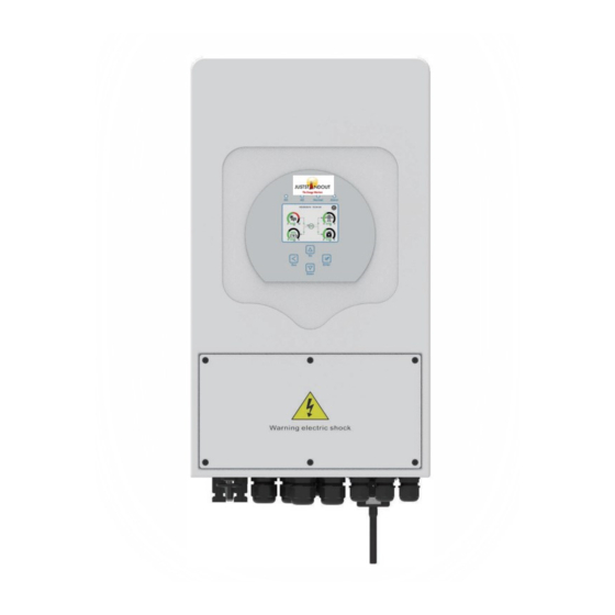
- Page 1 Hybrid Smart JUSTSTANDOUT SMART HYBRID INVERTER JSO12048156 User Manual...
- Page 2 Safety Introductions………………………………………………………..……………………………………….01 Product instructions………………………………………………………………….…………………………….01-04 Product Overview Product Size Product Features Basic System Architecture Installation……………………………………………………………………………………………………………..05-20 Parts list Mounting instructions Battery connection Grid connection and backup load connection PV Connection CT Connection Earth Connection(mandatory) WiFi Connection Wiring System for Smart inverter Typical application diagram of diesel generator Single phase parallel connection diagram 3.10 Three phase Parallel Smart inverter...
-
Page 3: About This Manual
Its comprehensive LCD display offers user configurable and easy accessible button operation such as battery charging, AC/solar charging, and acceptable input voltage based on different applications. If you need any clarification, please reach out our team at service@juststandout.com. - 01 -... - Page 4 1: Smart inverter 6: BMS CAN Port 14: Power on/off button Indicators 7: DRMs Port 15: DC Switch 8: Parallel port 2: LCD display 16: PV input with two 9: Function Port 3: Function Buttons MPPT 10: RS 485 Port 4: Battery input 17: Battery 11: Generator...
- Page 5 2.2 Product Size Mounting bracket - 03 -...
-
Page 6: Product Features
- Self-consumption and feed-in to the grid. 2.3 Product Features - Auto restart while AC is recovering. - Programmable supply priority for battery or grid. - Programmable multiple operation modes: On grid, off grid and UPS. - Configurable battery charging current/voltage based on applications by LCD setting. - Configurable AC/Solar/Generator Charger priority by LCD setting. -
Page 7: Installation
3. Installation Check the equipment before installation. Please make sure nothing is damaged in the 3.1 Parts List package. You should have received the items in the following package: Smart Hybrid inverter x1 Wi-Fi/GPRS dongle x1 - 05 -... - Page 8 3.2 Mounting instructions This Smart Hybrid inverter is designed for outdoor use(IP65), Please make sure the Installation Precaution installation site meets below conditions: Not in direct sunlight Not in areas where highly flammable materials are stored. Not in potential explosive areas. ...
- Page 9 ≥500mm For proper air circulation to dissipate heat, allow a clearance of approximate 50cm to the side and approximate 50cm above and below the unit. And 100cm to the front. Mounting the smart inverter Remember that this smart inverter is heavy! Please be careful when lifting out from the package.
-
Page 10: Battery Connection
3.3 Battery connection For safe operation and compliance, a separate DC over-current protector or disconnect device is required between the battery and the smart inverter. In some applications, switching devices may not be required but over-current protectors are still required. Refer to the typical amperage in the table below for the required fuse or circuit breaker size. - Page 11 All wiring must be performed by a professional. Connecting the battery with a suitable cable is important for safe and efficient operation of the system. To reduce the risk of injury, refer to Chart 3-2 for recommended cables. Please follow the steps below to connect the battery: 1.
- Page 12 - 10 - - 10 -...
- Page 13 3.3.3 Temperature sensor connection for lead-acid battery - 11 -...
- Page 14 Before connecting to grid, please install a separate AC breaker between smart inverter and 3.4 Grid connection and backup load connection grid. Also, it is recommended that you install an AC breaker between backup load and smart inverter. This will ensure that the smart inverter can be securely disconnected during maintenance and fully protected from over current.
- Page 15 Be sure that AC power source is disconnected before attempting to connect it to the unit. - 13 -...
- Page 16 3. Then, insert AC output wires according to polarities indicated on the terminal block and tighten the terminal. Be sure to connect corresponding N wires and PE wires to related terminals as well. 4. Make sure the wires are securely connected. 5.
- Page 17 When selecting proper PV modules, please be sure to consider the parameters below: 3.5.1 PV Module Selec 1) Open circuit Voltage (Voc) of PV modules does not exceeds maximum PV array open circuit voltage of smart inverter. 2) Open circuit Voltage (Voc) of PV modules should be higher than minimum start voltage. Smart inverter Model 12kW PV Input Voltage...
- Page 18 - 16 - - 16 -...
-
Page 19: Earth Connection(Mandatory)
3.6 CT Connection Note: when the inverter is in the off-grid state, the N line needs to be connected to the earth. 3.7 Earth Connection(mandatory) Ground cable should be connected to ground plate on grid side this prevents electric shock, if the original protective conductor fails. - Page 20 3.9 Wiring System for Smart inverter - 18 - - 18 -...
-
Page 21: Wiring Diagram
2,3. AC Breaker for battery JSO504865 40A AC breaker ① DC Breaker for battery JSO12048156: 250A DC breaker ② AC Breaker for grid and backup load JSO12048156: 80A AC breaker ③ ④ AC Breaker for grid and backup load JSO12048156: 20A AC breaker... - Page 22 3.11 Phase parallel connection diagram 1,2,3. DC Breaker for battery JSO504865: 150A DC breaker 4,6,8. AC Breaker for grid port JSO504865: 40A AC breaker 5,7,9. AC Breaker for backup load port 10. AC Breaker Depends on household load - 20 - - 20 -...
-
Page 23: Operation And Display Panel
4. OPERATION 4.1 Power ON/OFF Once the unit has been properly installed and the batteries are connected well, simply press On/Off button (located on the left side of the case) to turn on the unit. When system is not connected to a battery, but connect with either PV or grid, and ON/OFF button is switched off, LCD will still light up (Display will show OFF), In this condition, when switched on, by pressing on the ON/OFF button, select NO battery, so system can still work. -
Page 24: Lcd Display Icons
5. LCD Display Icons The LCD is touchscreen; the screen below shows the overall information of the smart 5.1 Main Screen inverter. 1. The icon in the center of the home screen indicates that the system is in the ‘Normal operation”... - Page 25 5.1.1 LCD operation flow chart Grid Graph - 23 - - 23 -...
- Page 26 5.2 Solar Power Curve Press the “Energy” button to enter into the power curve page *Note: this part info is not available for some LCD FW Press the “Energy” button to enter into the power curve page Press the “Energy” button to enter into the power curve page - 24 - - 24 -...
- Page 27 5.3 Curve Page-Solar & Load & Grid Solar power curve for daily, monthly, yearly and total can be roughly checked on the LCD, for more accuracy power generation, please check on the monitoring system. Click the up and down arrow to check power curve of different period. - 25 - - 25 -...
-
Page 28: System Setup Menu
5.4 System Setup Menu 5.5 Basic Setup Menu Factory Reset Password: 9999 - 26 - - 26 -... -
Page 29: Battery Setup Menu
5.6 Battery Setup Menu Battery capacity: it tells JSO smart hybrid smart inverter to know your battery bank size. Use Batt V: Use Battery Voltage for all the settings (V). Use Batt %: Use Battery SOC for all the settings (%). Max. - Page 30 Recommended battery settings Battery Type Absorption Stage Float Stage Torque value (every 30 days AGM (or PCC) 14.2v (57.6v) 13.4v (53.6v) 14.2v(57.6v) 3hr ) 14.1v (56.4v) 13.5v (54.0v) 14.7v (59.0v) 13.7v (55.0v) 14.7v(59.0v) Lithium Follow its BMS voltage parameters - 28 - - 28 -...
- Page 31 5.7 System Work Mode Setup Menu - 29 - - 29 -...
- Page 32 Solar Sell: “Solar sell” is for Zero export to load or Zero export to CT: when this item is active, the surplus energy can be sold back to grid. When it is active, PV Power source priority usage is as follows: load consumption and charge battery and feed into grid.
- Page 33 5.8 Grid Setup Menu - 31 - - 31 -...
- Page 34 5.9 Generator Port Use Setup Menu - 32 - - 32 -...
- Page 35 5.10 Advanced Function Setup Menu - 33 - - 33 -...
- Page 36 5.11 Device Info Setup Menu 6. Mode Mode I: Basic Mode II: With Generator - 34 - - 34 -...
- Page 37 Mode III: With Smart-Load Mode IV: AC Couple - 35 - - 35 -...
- Page 38 The 1st priority power of the system is always the PV power, then 2nd and 3rd priority power will be the battery bank or grid according to the settings. The last power backup will be the Generator if it is available. The energy storage smart inverter is designed according to the grid-connected opera 7.
- Page 39 Error Description Solutions 1. When smart inverter is in Split phase(120/240Vac) or GFDI _Relay_Failure code three-phase system (120/208Vac) system, the backup load port N line needs to connect ground; 2. If the fault still exists, please contact us for help. 1.
- Page 40 1. When in parallel mode, check the parallel communication cable connection and hybrid smart inverter communication address setting; Parallel CANBus fault 2. During the parallel system startup period, smart inverters will report F29 when all smart inverters are in ON status, it will disappear automatically;...
- Page 41 Error Description Solutions 1. Check the backup load connected, make sure it is in code allowed power range; AC Overcurrent fault 2. If the fault still exists, please contact us for help. No Utility 1. Please confirm grid is lost or not; 2.
- Page 42 Heat sink temperature is too high 1. Check whether the work environment temperature is Heat sink high too high; temperature failure 2. Turn off the smart inverter for 10mins and restart; 3. Seek help from us, if cannot go back to normal state. Under the guidance of our company, customers return our products so that our company can Chart 7-1 Fault information provide service of maintenance or replacement of products of the same value.
-
Page 43: Data Sheet
9. Datasheet Model JS128048156 Battery Input Date Battery Type Lead-acid or Li-lon Battery Voltage Range(V) 40-60V Max. Charging Current(A) 240A Max. Discharging Current(A) 240A Charging Curve 3 Stages / Equalization External Temperature Sensor Optional Charging Strategy for Li-lon Self-adaption to BMS Battery PV String Input Data Max. - Page 44 Output Over Current Protection Integrated Output Shorted Protection Integrated Surge Protection DC Type II / AC Type II Model JSO12048156 Certifications and Standards VDE 0126, AS4777, NRS2017, G98, G99, IEC61683, IEC62116, Grid Regulation IEC61727 Safety Regulation IEC62109-1, IEC62109-2 EN61000-6-1, EN61000-6-3, FCC 15 class B General Data Operating Temperature Rande(℃)
- Page 45 Definition of RJ45 Port Pin for BMS 10. Appendix I RS485 Pin 485_B 485_A CAN-H CAN-L 485_A 485_B BMS Port - 43 -...
- Page 46 1. Split Core Current Transformer (CT) dimension: 11. Appendix II (mm) 2. Secondary output cable length is 4m. - 44 -...
- Page 47 Ver : 1.0, 2021-4...
Need help?
Do you have a question about the JSO12048156 and is the answer not in the manual?
Questions and answers